Topic: DMD0202

Using the Link Wizard to Create New Communication Links
Clicking the New... button in the Links section of the Launchpad invokes the Link Wizard which will guide the programmer step-by-step through the process of creating a new communication link to a Do-more controller. The first dialog is used to select the communication port that is physically connected to the controller.
Select the Communication Port to Use
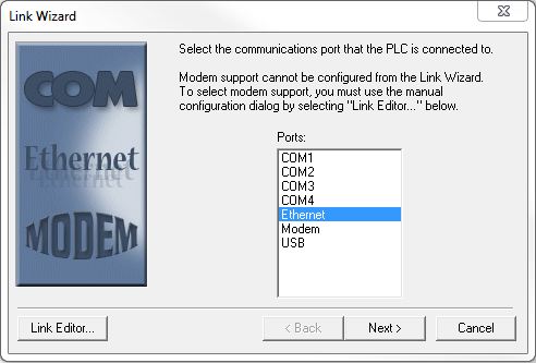
COM1, COM2, etc. - all of the serial communication ports that are configured on the PC will be listed here. Many of today's PCs do not have built-in serial ports but you can use a USB-to-Serial adapter as long as that adapter provides all of the necessary elements to completely emulate a serial port. Click to select the COM port to use. Refer to the Serial Port Communication Links section below for the next step.
Note: if the COM port you want to use is provided through a USB-to-Serial adapter, AND the USB cable was connected after Do-more Designer was started, that COM port may not be in the Ports list. If so, restarting Do-more Designer with the USB able attached to the Do-more CPU should add that COM port to the list so that it can be selected.
Ethernet - click this option to select the Ethernet port. Refer to the Ethernet Port Communication Links section below for the next step.
Modem - click this option to select the Modem. Refer to the Modem Communication Links section below for the next step.
USB - click this option to select the USB Port. Refer to the USB Port Communication Links section below for the next step.
Click the Link Editor ... button to bypass the remaining steps in the process and go directly to the Configure Link dialog which allows the programmer to manually enter all of the information required to create a new link.
Click the Next > button to proceed to the next step as defined by the selected the port.
Click the Cancel button to exit the Link Wizard without creating a new link.
Serial Port Communication Links
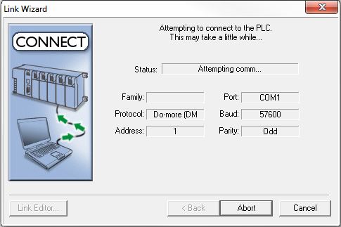
After clicking the Next button for a COM port, the Link Wizard will display a dialog that will use an "auto-baud" process to step through all of the available parity and baud rate combinations in an attempt to determine the correct settings and automatically create the serial communication link using those settings.
If the auto-baud process is successful the resulting dialog will Complete the link creation process.
Troubleshooting Serial Communication Link Problems
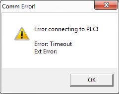
If the auto-baud process is NOT successful at finding a parity / baud rate combination that works the"Comm Error! - Error Connecting to PLC! - Timeout" message box will be displayed - depending on the situation, the following might be displayed instead:
"Comm Error! - No response from PLC!"
"Comm Error! - Error: cannot access comm port. The port may not be present or another application may be using it"
"Comm Error! - Error attempting to access unlocked device"
The most common reasons for failure when trying to create a communication link for a serial port are:
-
wrong cable - the cable being used between the serial port and the Do-more controller does not have the correct pin out
-
cable unplugged - the cable is not correctly (or completely) seated in the communication port of the Do-more controller, or in the serial port of the PC
-
port conflict - some software package - other than Do-more Designer - is currently using the selected serial port
-
wrong port selected - if the PC has multiple serial ports the wrong port may have been selected
Clicking the OK button will display the Link Error dialog which presents the following options:

Link Editor - this will open the Configure Link dialog where the programmer can manually change the communication parameters in an attempt to create a communication link.
< Back - this will return to the Port selection dialog so that a different port can be selected.
Exit - this will close the Link Wizard without creating a communication link.
Cancel - this will close the Link Wizard without creating a communication link.
Ethernet Port Communication Links
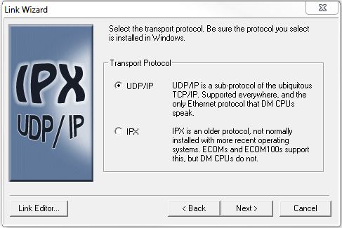
If Ethernet was selected as the port in the first step of the Link Wizard, the following additional information is required:
Transport Protocol - designates which Ethernet protocol to use
- IPX
- only supported when creating a link to the Do-more controller through
an ECOM100 module. IPX protocol is NOT available
on the Windows Vista, Windows 7 , or Windows 8+ operating systems.
- UDP/IP
- (TCP/IP) - is the only Ethernet protocol supported by the on-board
port of the Do-more controllers.
Link Editor - this will open the Configure Link dialog where the programmer can manually change the communication parameters in an attempt to create a communication link.
< Back - this will return to the Port selection dialog so that a different port can be selected.
Exit - this will close the Link Wizard without creating a communication link.
Cancel - this will close the Link Wizard without creating a communication link.
The next step of the Link Wizard for an Ethernet port is to select the target Do-more controller. Do-more Designer will issue an Ethernet broadcast query using the selected protocol, then display a list of the Do-more controllers that responded to the broadcast.
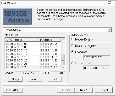
Adapter List - contains a list of the network adapters that are available for use on this PC. This list will have an entry for Default Adapter, an entry for each network interface card, and entries for any other network-capable devices (like VPNs). If the Default Adapter selection is not showing the correct list of Do-more controllers, click the drop-down arrow and select one of the other entries in the list. and click the Query button again.
Default
Adapter - this is the network adapter that Windows has selected
as the default for Ethernet communication.
additional adapters are listed by their manufacturer and their IP Address - each network interface card will have it's own entry.
Module List - displays the list of controllers and Do-more Simulators that responded to the broadcast query. If the Module list is empty refer to the troubleshooting section below.
Query
- reissues the broadcast query
Setup... - opens NetEdit utility where the Module ID, Name, Description, and IP Address of devices found in the Module List are initially set or changed. The default IP address for a Do-more controller is 255.255.255.255. This address is valid for responding to TCP/IP broadcasts, but it is NOT a valid address for establishing a point-to-point TCP/IP connection, so it must be changed to an address that is valid for the IP network that the controller will operate on. Refer to the troubleshooting section below for details on how to set the TCP/IP addressing information.
Blink - will cause the ERR led on the highlighted entry to blink for 15 seconds, this can be used to verify that the selected entry is the correct Do-more controller
Address
Mode - designates which of the following options to reference the
new communication link by:
-
Module ID - user assigned node number, this number is set via the DIP switch or NetEdit.
-
Name - User assigned 16 character name
-
IP Address - (the default for IP Protocol) - the user assigned TCP/IP address of the controller
-
Ethernet Address - (the default for IPX Protocol) - the factory assigned MAC address of the controller
Link Editor - this will open the Configure Link dialog where the programmer can manually change the communication parameters in an attempt to create a communication link.
Click the Back > button to return to the previous step of the Link Wizard.
Click the Next > button to attempt to communicate with the selected controller. If the attempt is successful the resulting dialog will Complete the link creation process.
Click the Cancel button to exit the Link Wizard without creating a new link.
Troubleshooting Ethernet Communication Link Problems
If the Module List is empty - this typically means the Do-more controller has an IP Address and/or Subnet Mask that makes it part of a different network. The most likely causes are:
The PC has more than one network interface cards (NICs) and Do-more Designer is using the wrong one.
This can be remedied by selecting the correct NIC from the Adapter List as described above.
Reassigning the IP Address
and/or Subnet Mask to match the PC that is running Do-more
Designer. This can be accomplished by any of the following:
Do-more Designer USB or Serial port - the preferred method for clearing or resetting the TCP/IP network parameters is to use Do-more Designer to connect to the controller through the on-board USB port, the on-board Serial port, or through an ECOM100 module in the base, then either clear the network configuration, or set the network parameters to functional values for the local network.
NetEdit 3 -> Restore Factory Defaults - restoring the factory defaults will reset the Module ID, Name, Description, IP Address, Subnet Mask and Gateway fields to their factory default values. This method requires that NetEdit 3 be able to locate the module on the local network. Be aware that this clears more than just the TCP/IP settings.
DIP switch setting / Mode switch operation - follow this link to the topic describing a series of Mode switch manipulations with a specific DIP switch setting that will reset the network settings to their factory defaults.
If the IP Address for the controller is 255.255.255.255 - this indicates the IP Configuration in the Do-more controller has not been set. Click the Setup... button to open NetEdit and locate the Do-more controller in the list of Devices that were found on the network. Double click on that entry in the list to open a dialog that can set the IP address information (IP Address, Subnet Mask, Gateway Address) of the controller's Ethernet port. Return to the Link Wizard and click the Query button to refresh the IP address information for the devices in the Module List. The Do-more controller's IP address should now be the values set in NetEdit, which are valid for a point-to-point connection.
If the attempt is made to establish a connection to the selected Ethernet Device is NOT successful the "Comm Error! - Error connecting to PLC! - Transport protocol error" message box will be displayed.
![]()
The most common reason for this failure when trying to create a communication link for an Ethernet port PC running Do-more Designer on a PC that has more than one NIC (network interface card). Temporarily disabling the NIC that will NOT be used to establish the connection is the easiest way to handle this situation. Refer to the Do-more Designer FAQ section on the web site for permanent ways to deal with PCs that have multiple NICs.
Clicking the OK button will display the Link Error dialog which presents the following options:
Link Editor - this will open the Configure Link dialog where the programmer can manually change the communication parameters in an attempt to create a communication link
Click the Back > button to return to the previous step of the Link Wizard.
Click the Next > button to attempt to communicate with the selected controller. If the attempt is successful the resulting dialog will Complete the link creation process.
Click the Cancel button to exit the Link Wizard without creating a new link.
USB Port Communication Links
If USB was selected in the first step of the Link Wizard, Do-more Designer will poll the PC for available USB ports, then display a list of the controllers that are currently attached to these ports.
USB ports that are already in use by another link will not be displayed in this list. If you need to use the same USB port for links to multiple controllers, make sure the USB port is not in use when the Link Wizard is being executed.

Currently Attached CPUs - lists the controllers that were found attached with a USB cable. Click to highlight the target controller.
Click the Refresh List button to return to poll the PC for available USB ports
Link Editor - this will open the Configure Link dialog where the programmer can manually change the communication parameters in an attempt to create a communication link
Click the Back > button to return to the previous step of the Link Wizard.
Click the Next > button to attempt to communicate with the selected controller. If the attempt is successful the resulting dialog will Complete the link creation process.
Click the Cancel button to exit the Link Wizard without creating a new link.
Troubleshooting USB Communication Link Problems
If the Currently Attached CPUs List is empty - this typically means there is a current Do-more Designer session already running that is using the USB port. This problem can only be resolved by closing the other session.

If you are still having trouble getting the USB port connection to the Do-more CPU to show up in this list, refer to the detailed troubleshooting information found in the Do-more CPU FAQ0025 at www.hosteng.com/faqfiles/do-more.htm
If the attempt is made to establish a connection through the selected USB Device is NOT successful the"Comm Error! - Error connecting to PLC! - Attempted access of unlocked device" message box will be displayed.
Clicking the OK button will display the Link Error dialog which presents the following options:
Link Editor - this will open the Configure Link dialog where the programmer can manually change the communication parameters in an attempt to create a communication link.
< Back - this will return to the USB Port selection dialog so that a different port can be selected.
Exit - this will close the Link Wizard without creating a communication link.
Cancel - this will close the Link Wizard without creating a communication link.
Modem Communication Links
If Modem was selected in the first step of the Link Wizard, Do-more Designer will initiate the process of creating a Modem connection. If the PC has not been previously configured for a Modem connection, Windows will prompt the programmer for the information required to establish modem connections from the operating system's viewpoint before it hands control back to Do-more Designer to acquire the remaining information.
Modem to Use - select a modem from the list of the modem devices configured on this PC
The Where
you're calling group designates the phone number for the
destination modem
Country
- select the country code from the list
Area Code
- enter the area code
Use Country
and Area Codes - enable this option to select a country code, leave
disabled to use only the area code
Phone Number - enter the phone number of the destination modem
The Your
Location designates the source phone number location
Select from among the list of predefined locations that are configured on this PC.
Link Editor - this will open the Configure Link dialog where the programmer can manually change the communication parameters in an attempt to create a communication link
Click the Back > button to return to the previous step of the Link Wizard.
Click the Next > button to proceed to the next step using the selected modem.
Click the Cancel button to exit the Link Wizard without creating a new link.
Complete the Creation of the Communication Links
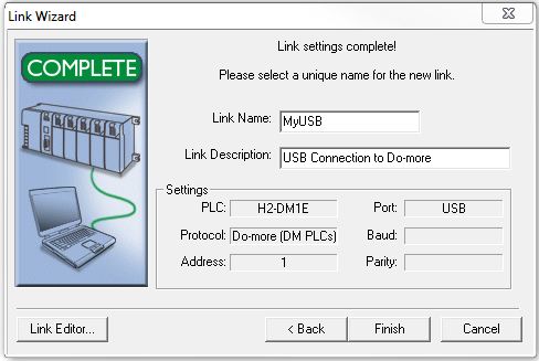
Regardless of which was selected in the first step of the Link Wizard, the Final Step of the Link Wizard will be to give the communication link a unique name and a description.
Link Name - is a 16-character name that must be unique on the PC running the programming software.
Link Description - is a 32 character text string the user enters to describe this communication link.
The Settings group will display
the communication parameters that will be saved with this link.
PLC - the CPU Type (typically the part number of the controller)
Protocol - the communication protocol that will be used by this link
Address - the node address assigned to the controller
Port - the computer port that will be used by this communication link
Baud - the Baud rate that will be used by this communication link (if applicable)
Parity - the Parity bit setting that will be used by this communication link (if applicable).
Link Editor - this will open the Configure Link dialog where the programmer can manually change the communication parameters in an attempt to create a communication link
Click the Back > button to return to the previous step of the Link Wizard.
Click the Finish > button to create the new communication link using the information collected through the Link Wizard process.
Click the Cancel button to exit the Link Wizard without creating a new link.
See Also:
Connecting to a Do-more Controller
Using the Link Wizard to Create New Communication Links
Using Configure Link to Modify Existing Communication Links
Using Link Info to Monitor Communication Links
Related Topics: