Topic: DMD0488
DMLOGGER - Broadcast String to DMLogger.exe
The Broadcast to DMLogger.exe (DMLOGGER) instruction is used to send user-created Strings from an Ethernet-equipped Do-more CPU to the Do-more Logger utility that will display the contents of the String. The Do-more CPU will use Ethernet broadcast packets to send the Strings to
Do-More Logger, which means the Do-more CPU and the PC running Do-More Logger must be in the same Broadcast Domain![]() A broadcast domain is a logical network segment in which any device connected to the network can directly transmit to any other on the domain without having to go through a routing device. These are typically very basic networks that use hubs rather than switches or routers. A special broadcast address consisting of all 1s is used to send frames to all devices on the network..
A broadcast domain is a logical network segment in which any device connected to the network can directly transmit to any other on the domain without having to go through a routing device. These are typically very basic networks that use hubs rather than switches or routers. A special broadcast address consisting of all 1s is used to send frames to all devices on the network..
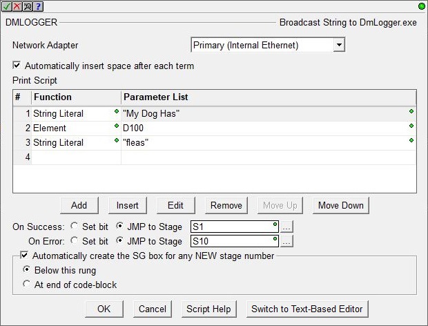
By default, the DMLOGGER instruction editor uses a table-style editor that works by building a series of commands with their required data parameters that will sequentially add content to the message body text. Each table entry is built by a sub-dialog which makes it very easy to correctly use the script functions and their required parameters.
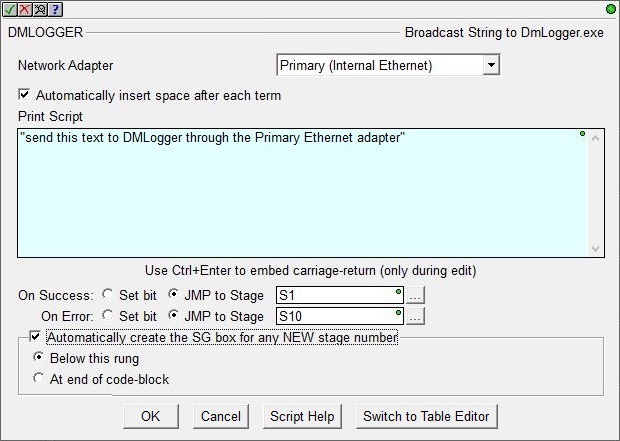
There is also a text-based editor that can be used by clicking the Switch to Text-Based Editor button at the bottom of the instruction editor. The text-based editor works by letting you enter the text data and script functions as a single entry. The text-based editor can be quicker for constructing simple Message bodies, or for those who don't need the assistance of the message print script function's sub-dialog editors.
Parameters:
Note: Use the F9 key or click the 'three dot box' at the right edge of the parameter field to open the Default Element Selection Tool (the Element Picker or the Element Browser) or use the Down-Arrow key (Auto-Complete) on any parameter field to see a complete list of the memory locations that are valid for that parameter of the instruction.
Network Adapter: because this instruction uses Ethernet broadcasts to send packets, you must select which of the Ethernet ports to send the packets through:
Default means the TCP stack will route the packets to the first Ethernet port that can process the packet; on CPUs without a Secondary port (BX-P-ECOMEX) this will always be the on-board port. This is also the proper selection for backwards compatibility with previous Do-more Technology versions and with H2-DM1E, T1H-DM1E, and BX-DM1 CPUs because they have no provision for a Secondary Ethernet port.
Primary (Internal Ethernet) will send packets through the on-board Ethernet port of the Do-more CPU.
Secondary (BRX ECOMEX) will send packets through the BRX CPU's secondary Ethernet port (BX-P-ECOMEX).
Checking Automatically insert space after each term will insert a space between the terms when the instruction is processed. This is most useful when the Message Field contains only a list of elements that would otherwise require a manually entered space character to separate the items.
For example, assume that V0 contains the value 1234, and V1 contains 5678, and V2 contains 9012.
If Message is specified as V0 V1 V2 and the 'Automatically insert space' is checked the result will be "1234 5678 9012".
If Message is specified as V0 V1 V2 and the 'Automatically insert space' is NOT checked the result will be "123456789012".
The same result can be created by manually inserting space characters in the Message like this: V0 " " V1 " " V2.
Print Script contains the PLC data, ASCII text, and script functions that will be processed to generate the output string. This can be any combination of PLC data elements, existing Strings, Sting Literals![]() Zero or more characters enclosed in double quotes, as in "hello", and may include both simple escape sequences (such as \t for the tab character) and hexadecimal data (such as 0xAA). (which can be both printable and control character escape sequences), and results from the data formatting functions.
Zero or more characters enclosed in double quotes, as in "hello", and may include both simple escape sequences (such as \t for the tab character) and hexadecimal data (such as 0xAA). (which can be both printable and control character escape sequences), and results from the data formatting functions.
Click OK to save changes, click Cancel to close the editor without saving any changes that were made, click Script Help to open the String Scripting Language Reference , or click Switch to Text-Based Editor / Switch to Table Editor to change back and forth between the two types of editors.
Using the Table-Style Editor to build the Message Body
After selecting Add, Edit, or Insert the sub-command editor will open where one of the available sub-commands can be selected and it's required parameters can be entered. The various sub-commands and their parameters are described in the sections that follow.
When the editing session is done, use the buttons at the bottom of the dialog as follows:
Save will save any changes that were made to the sub-command and close the row editor.
Save / Next will save any changes that were made to the sub-command, and begin an edit session for the next row in the table.
Save / Insert will save any changes that were made to the sub-command, and create a new command entry below the row that was just saved.
Cancel will close the row editor without saving any changes that have been made.
The following is a list of the available commands and their required parameters for constructing the message body text with the table-style editor:
Element
This function places data elements from the CPU memory into a string using the element's default display format. Any Bit (X0, Y0, C0, ...), numeric element (D0, R0, N0), constant value (3.14159, ...), or individual structure field (such as T0.Acc, MyPID.SP, MyProgram.RanThisScan, ...) can be specified.

String Literal
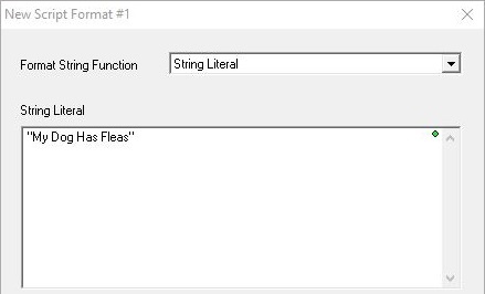
String literals are ASCII characters enclosed within a pair of double quotes.
"This string is being sent from a BX-DM1E-36ED13"
String Literals can also use $-based escape sequences to insert control characters in the text. Each of the codes is preceded by the '$' character.
"The price of part #1 is $$" FmtReal(R0, 5, 2, commas) "$T and part #2 is $$" FmtReal(R1, 5, 2, commas) "$N"
Note: in the ladder display, the $-based control character sequences (except for $$ and $") will be converted to their $hh form, e.g. "$N" will be displayed as "$0D$0A"
The chart below is a list of the available control characters that can be entered in the text:
FmtInt - Format an Integer Value
This function controls how integer numbers will appear in a String.
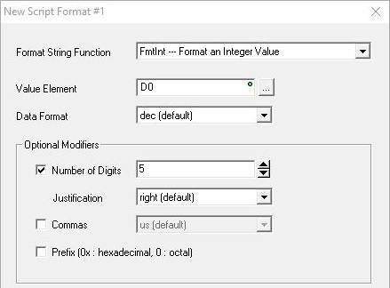
Value Element is the numeric value to format. This can be any readable numeric memory location or any constant value. If the value to format is NOT an integer, it will be converted to an integer then the modifiers will be applied. For example, if you specify a floating point (Real) location like R0, the value in R0 will be converted to an integer, then the modifiers will be applied.
Data Format selects how the value will appear in the String:
- dec (default) : decimal
- oct : octal
- hex : hexadecimal
- ipaddr : will format a DWord value in traditional TCP/IP Address format, that is, four numeric values between 0 and 255, separated by decimal points (192.168.100.200). No other format options are allowed when ipaddr is used.
Optional Modifiers control how the value will be displayed:
Number of Digits specifies how many digits to display in the String, from 2 to 255. The complete value will be displayed if the number of digits specified is too small.
Justification controls the alignment of the digits within the Number of Digits specified above (typically used to align columns of numbers):
- right will right justify the number and pad with leading spaces if needed.
- left will left justify the number and pad with trailing spaces if needed.
- zeropad will right justify the number and pad with leading zeros if needed.
Commas specifies whether commas will be placed in the result:
- us uses US style separators which places commas between each three digits of the number (1,000,000).
- eu uses European style separators which places periods between each three digits of the number (1.000.000).
Prefix will add a format-specific prefix to the value:
- 0x if the value is hex (0x3FFF).
- 0 if the value is octal (03777).
FmtReal - Format a Real (Floating Point) Value
This function controls how Real (floating point) numbers will appear in a String.
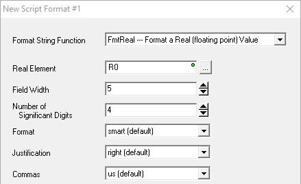
Real Element is the memory location that holds the Real (floating point) value to format. This can be any readable numeric memory location in the CPU. If the number to be formatted is NOT a Real number it will be promoted to a Real then the modifiers will be applied, for example, if you specify an integer (like D0), D0 will be converted to a Real, then the modifiers will be applied.
Field Width is the minimum number of digits to the left of the decimal point. This can be 1 to 255 digits. The value is not truncated even if the result is larger than the specified Field Width. If the value is shorter than the Field Width the result is padded with blank spaces.
Number of Significant Digits has different meanings based on the Format specified below:
For dec and exp format: it defines the number of digits to the right of the decimal point.
For smart format : it defines the total number of significant digits.
The range of valid values is 0 to 254; 255 has no effect for smart format. If there are fewer digits in the number than are specified, the number will be padded with zeros. If needed, the number will be rounded up.
Format
- dec will display the value as a full number in decimal notation (1500000000.0).
- exp will display the value in exponential form (1.5E10).
- smart (default) will display whichever is the shorter of dec or exp.
Justification controls the alignment of the digits within the Field Width specified above (typically used to align columns of numbers):
- right will right justify the number and pad with leading spaces if needed.
- left will left justify the number and pad with trailing spaces if needed.
Commas specifies whether commas will be placed in the result:
- us uses US style separators which places commas between each three digits of the whole number and a period to separate the whole number and the fraction (1,000,000.00).
- eu uses European style separators which places a period between each three digits of the whole number and a comma between the whole number and the fraction (1.000.000,00).
FmtBit - Format a Bit Value
This function controls how Bit values will appear in a String.

Bit Element is the memory location that holds the Bit value to format. This can be any readable Bit memory location.
Format selects the style of formatted text:
- val (default) will place the numeric value (0 or 1) of the bit location in the String.
- onoff will place the text " OFF" in the String if the value of the bit location is 0, and will place "ON" in the String if the value of the bit location is 1.
- truefalse will place the text " FALSE" in the String if the value of the bit location is 0, and will place "TRUE" in the String if the value of the bit location is 1.
TimeStamp - Format a Date / Time Stamp
Generates a Time Stamp (both Time and Date )from the CPUs real-time clock's current value.

Resolution selects the level of detail for the Time:
- min will not include seconds.
- sec (default) will include whole numbers of seconds.
- tenths will include tenths of a second.
- hundredths will include hundredths of a second.
- thousandths will include thousandths of a second.
Clock Time Type selects the formatted style of the text:
- local (default) will use $LocalTime which has been adjusted for time zone and daylight saving mode.
- utc will use UTC time with no adjustments.
FmtDate - Format a Date
This function formats the date portion of a Date / Time structure.

Date / Time Struct or Numeric is a location that contains the date information to format. This can be any system-defined Date/Time structure (SDT0 - SDT7), any user-defined Date/Time structure (UDT0 - UDTx), the .Date field of any Date-Time structure, or any DWord location containing a value that has been sourced from the .Date field of a Date/Time structure.
Format selects the style of the formatted date:
- us - m/d/yyyy specifies month (1 - 12) / date (1 - 31) / 4 digit year (1970 - 2038).
- eu - d/m/yyyy specifies date (1 - 31) / month (1 - 12) / 4 digit year (1970 - 2038).
- asia - yyyy/m/d specifies 4 digit year (1970 - 2038) / month (1 - 12) / date (1 - 31).
FmtTime - Format the Time
This function formats the time portion of a Date / Time structure.

Date / Time Struct or Numeric contains the time information to format. This can be any system-defined Date/Time structure (SDT0 - SDT7), any user-defined Date/Time structure (UDT0 - UDTx), the .Time field of any Date-Time structure, or any DWord location containing a value that has been sourced from the .time field of a Date/Time structure.
Format selects the style of the formatted time:
FmtString - Format a String
This function adjusts the length of a string and sets the left / center / right justification of the text within a string.
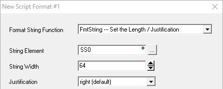
String Element contains the text to justify. This can be any writable user-defined String (max 1024 bytes), any system-defined Short String (SS0 - SS127, max 64 bytes), or any system-defined Long String (SL0 - SL63, max 256 bytes).
String Width is the maximum number of characters in the target string to work with.
Justification selects the position of the String Element text within the Width:
- Right (default) will position String Element in the rightmost characters of the target string, remaining characters to the left are filled with spaces.
- Center will position String Element in the central characters of the target string, remaining characters to the left and to the right are filled with spaces.
- Left will position String Element in the leftmost characters of the target string, remaining characters to the right are filled with spaces.
FmtTimer - Format a Timer Accumulator Value
This function controls how Timer Accumulator values will appear in a String.
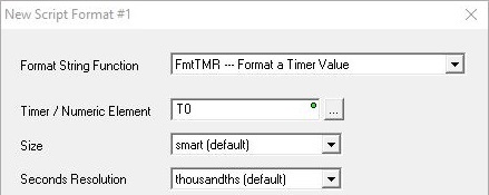
Timer Struct or Numeric contains the Timer information to format. This can be any system-defined Timer structure (T0 - T255), any user-defined Timer structure, or any numeric memory location.
Size selects how to format the Hours and Minutes information:
- smart (default) will only include the hours and minutes if they are not 0 (for example: 15m 43.385s).
- full will always display the hours and minutes (for example: 0h 15m 43.385s).
Seconds Resolution selects the amount of information about the seconds to display:
- sec will display only whole numbers of seconds (for example: 0h 15m 43s).
- tenths will display down to tenths of seconds (for example: 0h 15m 43.3s).
- hundredths will display down to hundredths of seconds (for example: 0h 15m 43.38s).
- thousandths (default) will display down to thousandths of seconds (for example: 0h 15m 43.385s).
Lookup - Select a String based on a Value
This function selects the string at the position indicated by the selector's value from the given list of strings. The first string in the list is selected when the selector's value is 0. The last string in the list is selected if the selector value is negative, or if the selector value is greater than the total number of strings in the list.
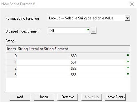
0-based Index Element is the numeric memory location that contains the value that selects the String. This can be any readable numeric memory location.
Strings is the list of Strings that correspond to the 0-based Index values. The list of strings can contain String literals, any writable user-defined String (max 1024 bytes), any system-defined Short String (SS0 - SS127, max 64 bytes), or any system-defined Long String (SL0 - SL63, max 256 bytes).
The buttons below the table provide functions for organizing the rows in the table: Add opens the row editor sub-dialog so that a new entry can be added to the end of the table. Insert inserts an empty row before the currently selected row / Edit opens the currently selected row in the row editor sub-dialog / Remove deletes the currently selected row. Move Up / Move Down moves the currently selected row up one row or down one row respectively.
Raw - Copy Bytes from Numeric Memory to a String
This function places bytes of data from numeric data blocks into a String. This is typically used when implementing a protocol driver that does not use ASCII characters for data.
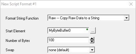
Start Element is the numeric data block that contains the source bytes. This can be any can be any readable Byte, Word, or DWord numeric memory location. Start Element must resolve to the address of a Byte memory location, so you cannot specify a single Bit element, or a constant value. You can however use a BYTE Cast to send 8 consecutive bits, for example X0:B would send bits X0- X7.
Number of Bytes is the number of consecutive bytes to put into the String. This can be any constant from 1 to 1023.
The Swap options can change the order in which the bytes will be placed in the String:
- none (default) means the Bytes will be placed into the String in the same order the appear in the memory block.
- bytes means the Bytes in each Word will be swapped.
- words means the Words in each DWord will be swapped.
- both means the Bytes in each Word will be swapped and the Words in each DWord will be swapped.
Fill - Fill a String with a Character
This function places the same hexadecimal constant in the specified number of consecutive locations in a String.

Hexadecimal Constant is the constant Hex value (0x00 to 0xFF) to place in the String.
Fill Length is the number of consecutive copies of the specified Hex Constant to place in the String
Using the Text-Based Editor to build the Message Body
When using the text-based editor, the Print Script is a single form that can contain any combination of PLC data elements (with or without data formatting functions), existing Strings, and Sting Literals![]() Zero or more characters enclosed in double quotes, as in "hello", and may include both simple escape sequences (such as \t for the tab character) and hexadecimal data (such as 0xAA). (which can be both printable and control character escape sequences). For a complete description of the available
data formatting functions for use in the Print Script,
see the Help reference for
the String Scripting Language.
Zero or more characters enclosed in double quotes, as in "hello", and may include both simple escape sequences (such as \t for the tab character) and hexadecimal data (such as 0xAA). (which can be both printable and control character escape sequences). For a complete description of the available
data formatting functions for use in the Print Script,
see the Help reference for
the String Scripting Language.
If the resulting contents of the Print Script exceeds 1023 characters of data, the Message Print Script will contain only the number of characters it can store - the remaining characters are lost - and a 'Buffer overflow' Warning will be generated.

The On Success and On Error parameters specify what action to perform when this instruction completes. You do not have to use the same type of selection for both On Success and On Error.
If the Set Bit selection is used for either On Success or On Error, the specified BIT location will be SET OFF when the instruction is first enabled and will remain OFF until the instruction completes. Once complete, the appropriate Success or Error bit location ON. The specified Bit location is enabled with a SET (Latch) operation meaning that it will remain ON even if the input logic for the instruction goes OFF.
If the JMP to Stage selection is used for either On Success or On Error the target Stage must be in the same Program code-block as this instruction, you cannot specify a target Stage that exists in a different Program code-block. When the operation finishes, the target Stage will be enabled the same way as a standalone Jump to Stage (JMP) instruction would do it. The JMP to Stage option will only be available if this instruction is placed in a Program code-block.
On Success selects which of the following actions to perform if the operation is successful:
- Enable SET Bit then specify any writable bit location.
- Enable JMP to Stage then specify any
Stage number from S0 to S127 in the current Program code-block.
On Error selects which of
the following actions to perform if the operation is unsuccessful:
- Enable SET Bit then specify writable bit location.
- Enable JMP to Stage then specify any Stage number from S0 to S127 in the current Program code-block.
If either the On Success or On Error selections are set to JMP to Stage, Automatically create the SG box for any NEW stage number will be enabled which will automatically create any target stage that does not already exist.
- Below this rung will create the new target stage on a new rung following this instruction.
- At end of code-block will create the new target stage as the last rung of this Program.
Status Display:
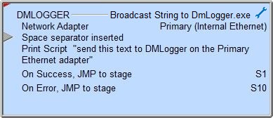
The gray triangle at the right end of an input leg indicates the input is edge triggered, meaning that each time the input logic transitions from OFF to ON the instruction will run one time to completion.
See Also:
Do-more Logger - Network Message Viewer
Related Topics:
STREAMOUT - Stream Out Data to Device
