Topic: DMD0205

Arrays, Pointers, Tables and Indirect Addressing
The most common form of addressing used in the Do-more CPU is direct. Direct addressing means that when a PLC memory item is referenced by an instruction there is only one location in memory being targeted. The following are some examples of direct addressing:
WX3 (analog input #3)
WY26 (analog output #26)
CT0 (Counter #0)
D106 (Signed DWord #106)
Indirect Addressing:
Indirect addressing allows the memory address used by an instruction to be varied so that it can point to more than one location at runtime. Used this way, one memory location stores a ”pointer” to another memory location. For example, if V17 has the value "37", then referencing D[V17] will return the value in the memory location D37. While this may initially increase the difficulty of troubleshooting, it has the advantage of greatly reducing the number of rungs and instructions needed to control a process.
The Do-more operating system implements all of the built-in and user-created data blocks as arrays, meaning that any of these data blocks can be indirectly addressed. All of the data blocks in the CPU's memory are limited to 65536 elements per block, so the array index value must be in the range of 0 to 65535. The array index can be either a single parameter stored in a V memory location ( e.g D[V17] ), or a math expression ( e.g. D[V17 + 16], or D[V17 + D18], or D[SQRT(D18)] ).
Both indirect addressing mechanisms (REF - Read Value Indirectly function and REFWRITE - Write Value Indirectly instruction) allow the use of any numeric value (or even any expression for REF function parameters) for the array index.
The indirect address can optionally include an offset value. For example, if V17 has the value "37", then referencing D[V17 + 3] will return the value in the memory location D40. The Offset value is limited to a maximum of 63.
Indirectly Addressing Bit Locations
All of the bit-memory data blocks in the CPU can be indirectly addresses. For example, if V17 has the value "37", then referencing C[V17] will return the value in bit location C37.
Indirectly Addressing Numeric Locations
All of the numeric data blocks in the CPU can be indirectly addresses. For example, if V17 has the value "37", then referencing R[V17] will return the value in the memory location R37.
Indirectly Addressing Structures and Structure Fields
Structures and individual structure fields can be indirectly addressed. For example, assume that V17 contains the value "37", then CT[V17] would be a valid reference to the structure used by Counter CT37, and CT[V17].Acc would be a valid reference to the Accumulator value of Counter CT37.
This is a simple example that uses a For / Next loop to iterate through 10 successive elements in a data block, adding together the values contained in each of the locations to calculate the sum.
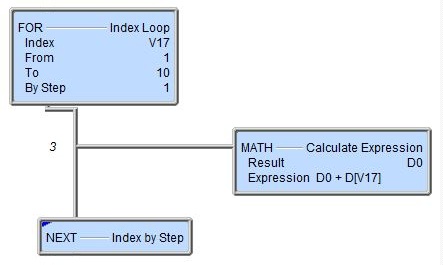
The Index Loop (FOR) instruction specifies that V17 will be used to store the value that will be used as the Index. The value of V17 will be initialized to 1 (specified in the From field), then each iteration of the loop will increment that value by 1 (as specified in the By Step field) to a maximum value of 10 (as specified in the To field).
The Calculate Expression (MATH) instruction will add the value in D0 to the value in location D[V17]. The first time through the loop V17 will contain the value 1, so the MATH instruction will calculate D0 = D0 + D1.
The next pass through the loop V17 will be 2, so the MATH instruction will calculate D0 = D0 + D2. This process will continue with D0 = D0 + D3 ... until it calculates D0 = D0 + D10.
Since the loop operated 10, and 1 was added each time, the result in D0 will be 10.
Sample Application: One Dimension Table
Assume the need to store multiple instances of a recurring value over some period of time, then perform some math calculations on that set of data points.
Create a new data block, named TempSample, of the required data type, in this example select Signed Word. The data block should have enough capacity to store the required number of samples, in this example enter 100.
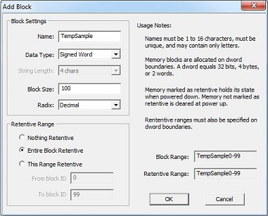
Notice the Block Range and Retentive Range fields show the new elements (TempSample0 - TempSample99) that will be available for use after this operation is complete.
The ladder logic to utilize this new data type as a one dimension table follows:
The first rung contains an Initialize Data (INIT) instruction that is executed only on the first PLC scan ($FirstScan).
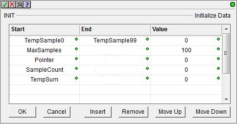
This Initialize Data instruction does the following:
-
clear the TempSample data block
-
specify the maximum number of sample to store
-
set the initial state of the pointer
-
clear the SampleCount register
-
clear the temporary summing register
The second rung does all of the work in storing successive value in the data block:
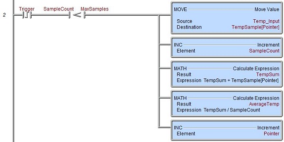
On the rising edge of each Trigger input, and as long as the current number of samples stored is less than the maximum number of samples that can be stored ...
-
Copy the current Temp_Input value to the TempSample data block element being
-
Add one to the SampleCount.
-
Add the value that was just stored in the TempSample data block to a temporary sum value.
-
Calcluate the average of all of the values currently stored in the TempSample data block.
-
Increment the Pointer so that it points to the next location in the TempSample data block.
Sample Application: Recipe Management
Assume the need\ to store multiple recipes, each with multiple ingredients, and provide random access to them at runtime. Expanding the one dimension table example to include multiple one dimension tables, this can be done quite effectively.
Create a new data block of the required data type for each 'ingredient' in a recipe. Each of the data blocks should be large enough to hold the maximum number of recipes.
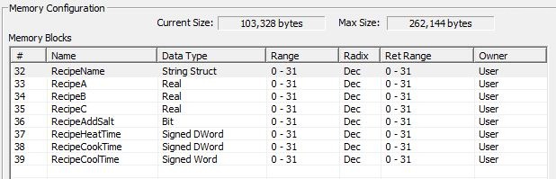
In this example there are eight new data blocks created, of varying types, with each capable of storing 32 elements.
An individual recipe now consists of the nth element in each of the newly created data blocks. For example, the name of Recipe 7 is in RecipeName7, ingredient A of Recipe 7 is in RecipeA7, the cook time of Recipe 7 is in RecipeCookTime7, etc. The individual data values for each element of each recipe is loaded into each of these memory blocks and saved to the PLC.
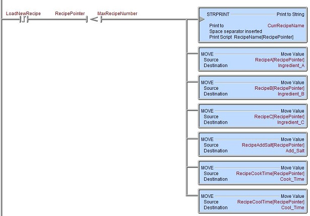
Providing random access to a recipe at runtime is done through a V memory location that is used as the 'recipe pointer'. To access the elements of a specific recipe do the following:
Set the contents of 'Recipe Pointer' to the required value, for example, if V17 is the recipe selector, set it to 23 to access recipe 23.
Use the required Print to String (STRPRINT) and Move Value (MOVE) instructions to copy the 'pointed to' values from the recipe data blocks to the memory locations in the CPU where they are used in the project.
This example copies the 'pointed to' elements of RecipeName, RecipeA, RecipeB, RecipeC, RecipeAddSalt, RecipeHeatTime, RecipeCookTime, and RecipeCoolTime to their respective destination locations in the CPU.
See Also:
User-Created Data Blocks and Structures
Arrays, Pointers and Tables
Assignment Operations and Instructions
Related Topics: