MB-Gateway Modbus/TCP -to- Modbus/RTU Gateway Updated: 09/28/2020
Specifications Firmware Documentation Wiring Diagrams FAQs
Modbus is one of the most popular communication protocols in the automation industry because it supports both traditional RS-232/422/485 serial devices and newly developed industrial Ethernet devices. Many industrial devices, such as PLCs, DCSs, HMIs, instruments, and meters use Modbus as their standard communication protocol. However, the Modbus protocols running over serial and Ethernet are so different that a communication gateway is needed as a bridge for integrating devices from these two disparate networks. The MB-Gateway is a Modbus TCP/IP (Ethernet) -to- Modbus RTU (Serial) Gateway which provides the necessary bridge to connect Modbus RTU (serial) products to Ethernet LAN’s.

The Modbus/TCP side of the Gateway acts as slave (or server) and supports up to 12 simultaneous Ethernet connections. The Modbus/RTU side acts as a Modbus/RTU master (or client) which provides multi-drop serial connections for up to 128 Modbus slave devices - the actual number of Modbus/RTU slaves will depend on their individual transceiver loads.

Internal Table of Automatic Reads

The Modbus Gateway can be setup to automatically read data from the Modbus RTU slaves and store that data in the Modbus Gateway's memory so that subsequent requests for that data can be delivered more quickly.

Configured with Web Browser

The Modbus Gateway supports DHCP protocol which it can use to obtain it's TCP/IP network configuration, or NetEdit3 (v3.8 or later) can be used to statically assign the Gateway's TCP/IP network configuration (preferred).

After the Modbus Gateway has it's network configuration in place, the remainder of the configuration is done using a web browser over an Ethernet connection; simply open your web browser and browse to the IP address of the gateway. Using a web browser to access the built-in web pages that configure the Gateway allows the Gateway to be managed from either a local or a remote location. The configuration options on the various configuration pages are very straightforward, and easily understood, allowing the gateway to be up and running in just a few minutes!
 

Specifications  
Ethernet Interface Port RJ-45
Speed 10/100Mbps (Auto-MDI/MDI-X)
Protection Built-in 1.5 KV magnetic isolation
Protocol Supported Modbus TCP/IP Slave (server)
Serial Interface Port 6-position terminal block
Supported Signal Lines RS-422 (5 wire) Signals:  Tx+, Tx-, Rx-, Rx+, GND

RS-485 (3-wire) Signals:   Data+, Data-, GND
Supported Baud Rates 300*, 600*, 1200*, 2400*, 4800, 9600, 14400, 19200, 38400, 57600, 115200
*cannot be set with DIP switches, must be set via s/w configuration
Parity Odd, Even, None
Data Bits 1, 2
Stop Bits 1, 2
Protocol Supported Modbus RTU Master (client)
Power Consumption 220mA @ 10VDC / 70mA @ 24VDC / 50mA @ 36VDC

Use Class 2 power supply.

Use conductors rated 60/75ºC.
Recommended Cable Belden 9729 or equivalent
Wire Range (Rated Cross Section) 16 - 28AWG Solid or Stranded Conductor (1.5mm²)
Wire Strip Length 0.24 - 0.27" (6 - 7mm)
Screw Torque 1.7 in-lbs (0.2Nm)
Operating Environment 0 – 60 ºC (32 – 140 ºF)
5% to 95% humidity (non-condensing)

no corrosive gases, pollution level=2

Vibration: MIL STD 810C 514.2
Shock: MIL STD 810C 516.2
Storage Temperature -20 ºC – 70 ºC  (-4 ºF – 158 ºF)
Manufacturer Host Automation Products, LLC
Firmware

MB-GATEWAY
Last Update   : 7 December 2021

F/W Version   : v1.0.689
Boot Version  : v5.0.53

H/W Rev 7A)
Last Update   : 7 December 2021

F/W Version   : v7.0.66
Boot Version  : v7.0.1

View the MB-Gateway Revision History


Documentation
LED Descriptions
STA - Gateway Status
ON = Gateway passed power-up diagnostics
OFF = Gateway failed power-up diagnostics
 
ERR - Error
ON = Gateway has a critical failure
OFF = Gateway is Ok
FLASHING (once per second) = Firmware Upgrade in progress
FLASHING (randomly) = Modbus/RTU Error (Timeout or Error Response)
SPD - Ethernet Speed
ON = 100Mbps
OFF = 10Mbps
LK/A - Link Good / Activity
OFF = Module Failure
FLASHING = Ethernet Activity
TXD - Serial Port Transmit Data
FLASHING = Sending Data
RXD - Serial Port Receive Data
FLASHING = Receiving Data

Setting Up Automatic Reads

The Modbus Gateway can be setup to automatically read 16 individual blocks of data from the Modbus/RTU slaves and store that data in the Modbus Gateway's internal memory. Once the Automatic Reads table has been configured, the Gateway will continually run through the entries in the table and process them as quickly as possible. From that point on, any time the Gateway receives a read request for data that is automatically being read, the Gateway will return the data from it's internal memory instead of issuing a read request from the Modbus/RTU slave. If the read request is for data NOT being automatically read, the Gateway will issue a read request for the data from the Modbus/RTU slave and return that data in the TCP/IP response.

Memory to Read

Select one of the four available memory types to read (Coils, Discrete Inputs, Holding Registers or Input Registers)

Slave Number

The Unit ID of the Modbus/RTU slave from which to read the data.

RTU Start Address

The Offset in the Modbus/RTU slave of the data to read.

Number of Elements

The number of elements of the specified memory type to read from the Modbus/RTU slave.

  • The maximum number of Coils or Discrete Inputs in a single automatic read is 2000.
  • The maximum number of Holding Registers or Input Registers in a single automatic read is 125.

Gateway Memory Address

This field displays the starting location of the data from the automatic reads in the Gateway's internal memory. By default the Gateway will store the data from the individual automatic reads for the same memory types in consecutive location in the Gateway's internal memory.

For example, assume there are are two automatic reads configured to read 16 coils from each of two slaves, the Automatic Reads table would look like this:

Memory to Read Slave Number RTU Start Address Number of Elements Gateway Memory Address
1-Coils 1 0 16 0
1-Coils 2 0 16 16

The last column tells you that the Coil data from Modbus/RTU slave 1 will be stored in the Gateway in coil locations 0-15, and the Coil data from Modbus/RTU slave 2 will be stored in the next 16 coil locations in the Gateway which are 16-31.

The advantage of having this data is stored in consecutive data locations in the Gateway's internal memory is the ability to read all 32 of these coils in one request by specifying the Unit ID of the Gateway as the RTU slave in the read request. Using the above example, reading 32 coils beginning at offset 0, from the Unit ID of the Gateway itself would return the 16 coils from Unit ID 1 and the 16 bits from Unit ID 2 in a single transaction.

Gateway Modbus Address

This is the Unit ID of the Modbus Gateway itself. The Unit ID of the Gateway is set by NetEdit (v3.8 or later).

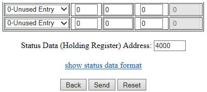
Auto Assign Gateway Addresses

If checked, the Gateway will automatically assign the internal memory locations for data from Automatic Reads. If unchecked this allows the user to manually assign the location on the Gate way to store the data. Care must be taken not to allow the data from different Automatic Reads to overlap in the Gateway's internal memory. If you do specify an Automatic Read that will create overlapping data, the value in the Gateway Memory Address field for that Read will be displayed in the color red.

For example, you could manually assign the internal address beginning location for slave 1's data to 100, then slave 2's data to begin at 200, etc.

Memory to Read Slave Number RTU Start Address Number of Elements Gateway Memory Address
1-Coils 1 0 16 100
1-Coils 2 0 16 200

Automatic Read Status Data

The final selection on this page is the Status Data (Holding Register) Address which allows the user to map a data area into Modbus Holding Register memory which will report the health of each of the automatic read operations. These 17 consecutive Holding Registers area can then be read from the Modbus Gateway (using the Gateway Modbus Address as Unit ID in the MRX instruction) for monitoring the Automatic reads by the Modbus/TCP Client.

Click the "show status data format" link to display a page that explains the layout of the data. The first register contains 1 Bit for each of the possible 16 Automatic Reads. Bit 0 = 1st Automatic Read Operation, Bit 1 = 2nd Automatic Read Operation, ... Bit 15 = 16th Automatic Read Operation.

A value of 1 in a Bit location means the last Automatic Read operation that corresponds to that Bit worked and the resulting data is valid.

A Value of 0 in a Bit location means the the last Automatic Read operation that corresponds to that Bit DID NOT work, and the Error Count for that Read Operation was incremented.

For example: if the Status Data is set to V4000, the data layout will be as follows:


Logging Requests

Using the SMTPViewer (download and install it in the \HAPTools folder), you can see the TCP and RTU requests that are being processed by the MB-Gateway. This logging feature will only send packets to the PC that requested the logging; therefore it is not using broadcast packets, and each Gateway can only log data to 1 PC at a time.

To use logging, connect to an MB-Gateway with SMTPViewer (UDP only; port 0x7272)  and issue the following command:

‘Log [req] [rsp] [rtu] [tcp] [dev #] [raw]’

req = Log requests
rsp = Log responses
rtu = Log RTU transactions
tcp = Log TCP transactions
raw = Show raw bytes instead of decoding transactions
dev # = Ex ‘dev 1’ would show only transactions for device 1

So, to see all rtu transactions (requests and responses) to/from device 1 in a decoded form:
‘Log rtu req rsp dev 1’

The command ‘log’ by itself defaults to ‘log req rsp rtu tcp’ which will show all requests and responses for all devices in a decoded form. All forms of the log command toggles from on to off, so you can issue the same command again to turn logging off.
 

Wiring Diagrams