Topic: DMD0336

Communication Ports
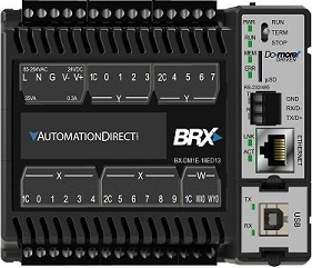
The BRX PLCs (BX-DM1-x and BX-DM1E-x) have one on-board RS-232 / RS-485 serial port and one POM slot where one additional communication POM can be added. The BX-DM1E PLCs additionally have one on-board 10/100Base-T Ethernet port.
|
BRX-DM1E-18
|
BRX-DM1E-36

shown with optional USB POM
|
|
BRX-DM1E-10
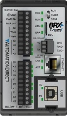
shown with optional USB POM
|
BRX-DM1E-M
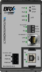
shown with optional USB POM
|
Both Do-more CPUs for the DirectLOGIC 205 Series have one built-in USB port (for programming with Do-more Designer), and one built-in RS-232 serial port. The H2-DM1E additionally has one on-board 10/100Base-T Ethernet port.
|
H2-DM1  |
H2-DM1E 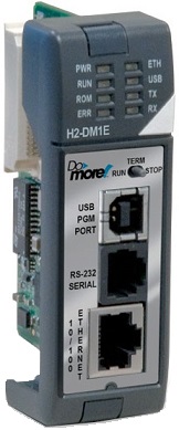
|
Both Do-more CPUs for the Terminator I/O Series have one built-in USB port and one built-in RS-232 serial port. The T1H-DM1E additionally has one on-board 10/100Base-T Ethernet port.
|
T1H-DM1 
|
T1H-DM1E 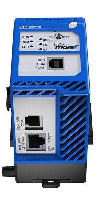
|
On-board USB Port
The on-board USB port on the H2-DM1 / H2-DM1E and T1H-DM1 / T1H-DM1E CPUs is a USB-B port that can only be used with Do-more Designer for programming, debugging, and monitoring. The port supports USB v1.0, v1.1, and v2.0.

On-board Serial Ports
The on-board RS-232 serial port on the H2-DM1 / H2-DM1E and T1H-DM1 / T1H-DM1E CPUs use an RJ-12 (6P6C), telephone-style jack. The maximum buffer size is 1024 bytes.
|
RJ-12 Modular (6P6C) |
|||

|
1 |
||
|
2 |
5V |
5VDC @ 200mA |
|
|
3 |
Receive Data |
||
|
4 |
Transmit Data |
||
|
5 |
|||
|
6 |
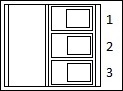
The on-board serial port on the BRX-DM1 / BRX-DM1E CPUs use a 3 pin connector. This serial port can be configured (in the System Configuration) to operate as either RS-232 or RS-485. The maximum buffer size is 1024 bytes.
| 3 Pin Removable Connector |
Pin Number |
Pin Name |
Description |
|
1 |
GND |
Signal Ground
|
|
2 |
RX / D- |
Receive data (RS-232) Data + (RS-485) |
|
|
3 |
TX / D+ |
Transmit data (RS-232) Data - (RS-485) |
These serial ports can be configured to support one of several operation modes in the CPU's Serial Port Configuration section of the System Configuration utility. The operational mode selection will determine the Device and the associated structure that are created to give your project runtime access to the serial port.
Setting the port's parity, baud rate, slave ID, etc. can be done at the same time the operational mode is selected or they can be set at runtime with the Setup Serial Port (SETUPSER) instruction.
The on-board serial port can be configured to perform any of the following functions:
Do-more Designer programming, debugging, and monitoring.
Modbus RTU Master (Client) when the port is used by the MRX - Modbus Network Read and MWX - Modbus Network Write instructions.
Modbus RTU Slave (Server) which makes the Modbus protocol memory (MC, MI, MHR, MIR) available to external Modbus RTU clients.
ASCII Input / Output (full duplex) when the port is used by the STREAMIN - Stream In Data from Device and STREAMOUT - Stream Out Data to Device instructions.
DirectLOGIC AIN / PRINTV users see note below
DirectLOGIC Master (Client) when the port is used by the DLRX - DirectLOGIC Network Read and DLWX - DirectLOGIC Network Write instructions.
K-Sequence Slave (Server) which makes the DirectLOGIC protocol memory (DLX, DLY, DLC, DLV) available to external K-Sequence clients.
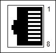
On-board Ethernet Port
The on-board Ethernet port on the DM1E CPU is 10/100Base-T Ethernet port with an RJ-45 jack that supports Auto-MDI/MDIX which means that it will can make a connection over either a “straight through” cable or a “crossover” cable.
|
RJ-45 Modular |
Pin Number |
Pin Name |
Description |
|
1 |
TXD + |
Transmit Data + |
|
2 |
TXD - |
Transmit Data - |
|
|
3 |
RXD+ |
Receive Data + |
|
|
4 |
n/c |
not used |
|
|
5 |
n/c |
not used |
|
|
6 |
RXD - |
Receive Data - |
|
|
7 |
n/c |
not used |
|
|
8 |
n/c |
not used |
Setting up the TCP/IP network parameters for the Ethernet port is done with NetEdit (v3.81 or later), or on the General Information tab of the System info utility in Do-more Designer.
This
port can concurrently support any combination of the following operations:
Do-more Designer programming, debugging, and monitoring.
Ethernet I/O Master for any combination of up to 16 BX-DMIO, BX-EBC100-x, H2-EBC100, T1H-EBC100 or GS-EDRV100s as Ethernet I/O Slaves. When this port is used as an Ethernet I/O Master it is recommended that other functions that require Ethernet connectivity be off-loaded to an ECOM100 to make the I/O network as stable and as fast as possible.
EtherNet/IP Explicit Message Server can be enabled / disabled, and configured in the CPU Configuration section of the System Configuration utility.
EtherNet/IP Explicit Message Client allows use of the Send EtherNet/IP Message (EIPMSG) instruction.
Modbus TCP Master (Client) allows use of the MRX - Modbus Network Read and MWX - Modbus Network Write instructions.
Modbus TCP Slave (Server) can be enabled / disabled, and configured in the CPU Configuration section of the System Configuration utility.
ASCII Input /Output when used by the STREAMIN - Stream In Data from Device and STREAMOUT - Stream Out Data to Device instructions for TCP connections, use the PACKETIN - Input Data from Packet Device and PACKETOUT - Output UDP to Packet Device instructions for UDP connections.
DirectLOGIC Master (Client) allows use of the DLRX - DirectLOGIC Network Read and DLWX - DirectLOGIC Network Write instructions.
Send Email allows use of the EMAIL - Send Email instruction.
Send to / Receive from an IoT (Internet of Things) network with the MQTTPUB - IoT Publish MQTT Topics and MQTTSUB - IoT Subscribe to MQTT Topics instructions.
Send to / Receive from to a web server with the HTTPCMD - Execute HTTP Command instruction.
Share data with other Do-more PLCs or ECOM100s through the PEERLINK - Share Data with PLCs. instruction.
Retrieve clock and calendar information from a Network Time Server with the NETTIME - SNTP Client instruction.
Synchronize the clocks on multiple Do-more PLCs with TimeSync which is configured in the CPU Configuration section of the System Configuration utility.
Capture and display debug and status messages received from an Ethernet-equipped Do-more CPU with the Network Message Viewer (Do-more Logger) utility.
TCP and UDP Port Numbers Used by the On-board Ethernet Port
TCP and UDP use port numbers to identify source and destination applications. For typical client-server protocols such as those used for Web and Email access, a client computer specifies the port to use when it initiates the communication. The server application is typically listening on a preconfigured TCP or UDP port. The following is a list of Internet socket port numbers used by the various processes and protocols in the Do-more CPU for the establishment of host-to-host communications. These are the port numbers that may need to be "opened up" on network routers to allow certain Do-more network functions to work.
|
Do-more Application or Instruction |
Description |
Default Port number |
Configurable |
|
|
|
|
Decimal |
|
|
|
configured in the Device Configuration section
used by the EMAIL
- Send Email instruction |
25 |
19 |
Yes |
|
|
NETTIME - SNTP Client |
used in the NETTIME
- SNTP Client instruction to retrieve clock and calendar information
from a Network Time Server |
123 |
7B |
Yes |
|
configured in the CPU
Configuration section |
502 |
1F6 |
Yes |
|
|
Modbus/TCP Clients |
configured in the CPU Configuration section
used in the MRX
- Modbus Network Read and MWX
- Modbus Network Write instructions |
502 |
1F6 |
Yes |
|
EtherNet/IP Server |
configured in the CPU
Configuration section |
44818 |
AF12 |
Yes |
|
Do-more Designer |
the programming, debugging, and monitoring software |
28784 |
7070 |
No |
|
TimeSync |
configured in the CPU
Configuration section |
28784 |
7070 |
No |
|
On-board Ethernet I/O |
used by Do-more's built-in Ethernet I/O Master to configure and communicate with it's slaves
|
28784 |
7070 |
No |
|
PEERLINK |
use the PEERLINK
- Share Global Data instruction |
28784 |
7070 |
No |
|
NetEdit |
NetEdit is used to initially configure the TCP/IP settings
|
28784 |
7070 |
No |
|
used by Do-more Logger to capture and display debug and status messages
|
29298 |
7272 |
No |
|
|
UDP Connection |
configured in the Device
Configuration section
|
User Defined |
User Defined |
Yes |
|
TCP Server |
configured in the Device Configuration section used by the OPENTCP
- Open TCP Connection |
User Defined |
User Defined |
Yes |
Communication Pluggable Option Modules (POM)
All of the BRX CPUs contain at least one slot where one of the communication POM (Pluggable Option Module) devices can be installed. POMs are hot-swappable which means they can be installed or removed while the BRX PLC is powered up. POMs can be configured in the POM Configuration section of the System Configuration utility.
Serial Communication POMs
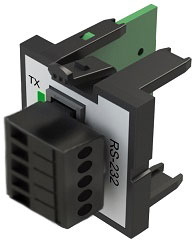
There are five Serial Communication POMs that provide connections for external serial devices. They vary by the connector type and the signal interface.
|
BX-P-SER2-RJ12

RS-232 using an RJ-12
|
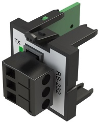
RS-232 using a 3-position terminal block
|

RS-485 using a 3-position terminal block (selectable 120 ohm termination resistor) |
BX-P-SER2-TERMFC
RS-232 with hardware flow control using a 5-position terminal block
|
BX-P-SER422-TERM
RS-422 using a 5-position terminal block
|
|||||||||||
|
|
|
|
|


These serial communication POMs can be configured to support one of several operation modes in the POM Configuration section of the System Configuration utility. The operational mode selection will determine the Device and the associated structure that give your project runtime access to the serial port. Setting the port's parity, baud rate, slave ID, etc. can be done at the same time the operational mode is selected, or they can be set at runtime with the Setup Serial Port (SETUPSER) instruction.
Do-more Protocol ( for Programming, HMIs, etc.).
Modbus RTU Client (Master) when the port is used by the MRX - Modbus Network Read and MWX - Modbus Network Write instructions.
Modbus RTU Server (Slave) which provides access to the Modbus protocol memory (MC, MI, MHR, MIR) to external Modbus RTU clients.
ASCII Input / Output (full duplex) when the port is used by the STREAMIN - Stream In Data from Device and STREAMOUT - Stream Out Data to Device instructions.
Note: DirectLOGIC AIN / PRINTV Users: the hardware used in the on-board serial port, the BX-P-SER2-RJ12, the BX-P-SER2-TERM, and the serial ports on the BX-SERIO operate in full duplex mode, meaning the hardware can receive data into its input buffer at the same time it is sending data from its output buffer. This means you don't have to worry about the turn-around time to prevent missing or overwriting data like you do when using the AIN and PRINTV instructions in a DirectLOGIC PLC.
Note: Full Duplex: The Do-more CPUs utilize a device driver to control access to the serial ports. This device driver only allows one instruction at a time to have access to the serial port hardware, which effectively restricts the PLC program to half duplex operation. This is typically not an issue for two reasons: (1) most communication protocols are half-duplex by design, and (2) access to the data in the hardware's input and output buffers are so fast that the STREAMOUT and STREAMIN instructions can run on successive PLC scans.
K-Sequence Server (Slave) which provides access to the DirectLOGIC protocol memory (DLX, DLY, DLC, DLV) to external K-Sequence clients.
Ethernet Communication POMs
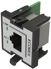
BX-P-ECOMEX
This POM is secondary Ethernet port for BRX CPUs that already have an on-board Ethernet port (BX-DM1E-xxx). Because it is a secondary Ethernet port, the CPU's TCP stack will route the Ethernet packets through the proper Ethernet port based on the destination IP address. To make the routing work the ECOMEX must have a TCP/IP configuration that places it on a different subnet than the on-board Ethernet port. This is analogous to having a second NIC in your PC in that they too must be on different subnets. Note: since this POM is only a secondary Ethernet port, it will not work in BRX CPUs that do not already have a primary (on-board) Ethernet port (BX-DM1-xxx). The TCP/IP address configuration for the BX-P-ECOMEX can only be setup through these selections in the System Configuration; this setup cannot be done through NetEdit.
Any PLC function (e.g. Ethernet I/O Master, TimeSync, etc.) or any PLC instruction (e.g. EMAIL, RX, MRX, etc.), that can use the on-board Ethernet port can use the ECOMEX as well. This allows segmenting the TCP/IP traffic into two independent domains. The CPU will route the Ethernet packets for the different functions and instructions to the correct Ethernet port based on the subnet used in each subnet.
BX-P-ECOMLT
This POM provides a 10/100Base-T Ethernet connection to external Do-more protocol clients, such as the Do-more Designer programming software and C-More HMI panels. The Ethernet port on the ECOMLT is an RJ-45 jack that supports Auto-MDI/MDIX which means that it will can make a connection over either a “straight through” cable or a “crossover” cable.
Before the ECOMLT can operate properly it must be configured with an IP Address, Subnet Mask, and Gateway Address. These required parameters can be provided from any of the following sources:
A DHCP server can provide the required information. Setting the IP Address, Subnet Mask and Gateway Address to 0.0.0.0 will put the ECOMLT into DHCP mode.
The NetEdit (v4.14 or later)utility can be used to assign static values for the address information.
The POM Configuration section of the System Configuration can be used to override the IP configuration data of any ECOMLT by providing the IP Address, Subnet Mask and Gateway Address for the ECOMLT to use while it is plugged into the POM slot. This does not change the ECOMLT's static IP configuration, it only overrides the IP configuration for the ECOMLT while the ECOMLT is plugged into this BRX PLC.
The Setup TCP/IP Parameters (SETUPIP) instruction can be used to set the IP configuration from ladder logic. This instruction does change the static IP configuration of the ECOMLT.
|
BX-P-ECOMEX
10/100 Base-T with RJ-45 socket
|
BX-P-ECOMLT
10/100 Base-T with RJ-45 socket
|
||||||||
|
|

USB-B POM
The USB POM provides a USB-B port that can only be used with Do-more Designer for programming, debugging, and monitoring. The port supports USB v1.0, v1.1, and v2.0.
|

USB-B socket
|
||||||
|
See Also:
System Setup and Maintenance Overview
Configuring the Hardware Watchdog Timer
Mode Switch Position Definitions
Configuring the On-board Ethernet Port