Topic: DMD0022

FREQCNT - Frequency Counter
The Frequency Counter (FREQCNT) instruction is used to convert the rate of a series of pulses to engineering units by sampling the counts for a period of time, normalizing that value to the desired time base, then scaling that value to the desired engineering units. This type of scaling is typically done for speed, flow rate, velocity, etc.. The Frequency Counter is always enabled, meaning that the output value is constantly being generated based on the frequency of the input pulses. This means the output value is constantly being updated.
This instruction operates in a similar manner to the Rate Scaling and Position Scaling operations in the CTRIO modules.
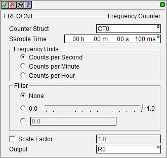
Parameters:
Note: Use the F9 key or click the 'three dot box' at the right edge of the parameter field to open the Default Element Selection Tool (the Element Picker or the Element Browser) or use the Down-Arrow key (Auto-Complete) on any parameter field to see a complete list of the memory locations that are valid for that parameter of the instruction.
Counter Struct is the Counter structure that this instruction will use. This can be any of the system defined Counters (CT Data Block), or any user defined Counter.
Sample Time is the amount of time to sample the incoming pulse rate. The Sample Time is specified using the Time format (HH : MM : SS : mmm). The maximum Sample Time value in this form is 569 hours, 31 minutes, 23 seconds, and 647 milliseconds. If needed, the value entered for the Sample Time will be normalized to its standard value. For example, if you entered a value of 97 Seconds, that value will be converted and displayed as 1 Minute and 37 Seconds.
Frequency Units specifies the output scaling factor:
-
Counts per Second will scale the input pulse count to Counts per Second.
-
Counts per Minute will scale the input pulse count to Counts per Minute.
-
Counts per Hour will scale the input pulse count to Counts per Hour.
Filter enables a filtering
algorithm that is applied during the calculation that defines how much
'weight' the current-value is given versus the latest-calculated-value.
Filtering acts as a data smoothing function, balancing stability versus
the responsiveness of the calculated value as it responds to changes in
the input pulse rate. A large filter value gives more weight to the latest-calculated-value
(and hence less weight to the current-value), producing a more stable
value that responds more slowly to changes in the input pulse rate. A
small filter value gives less weight to the latest-calculated-value (and
hence more weight to the current-value), producing a less stable value
but it responds more quickly to changes in the input pulse rate.
-
None will disable the filtering algorithm.
-
0.0 - 1.0 : Sliding Scale : sliding the slider to the right increases the filter constant. The sliding scale is a logarithmic (non-liner) scale, the mid point of the filter value is about 1/3 of the scale.
-
0.0 : Constant Value can be any constant floating point value between 0.0 and 0.999999.
Scale Factor will optionally apply an additional scaling factor to the calculated value, for example, to convert counts per second to engineering units like gallons per seconds.
Output is a numeric memory location to store the output value. This can be any writable REAL (floating point) location.
Termination Scan Behavior:
If the Frequency Counter instruction is contained within a Program, a Task, or a Stage, it will automatically be reset during the termination scan of that Program, Task, or Stage. Refer to the Help topic on Termination Behavior for detailed information on the programming elements that have termination logic.
Status Display:
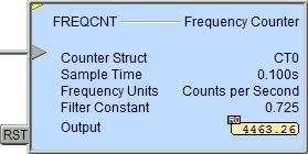
The yellow triangle in the upper left corner indicates this is a Multi-Scan instruction.
The first input leg is the Count Input. The gray triangle at the right end of an input leg indicates the input
is Edge Triggered.![]() Each time the input logic transitions from OFF to ON this instruction will execute. With each execution, this instruction will run to completion even if the input logic transitions to OFF before the instruction completes.
Each time the input logic transitions from OFF to ON this instruction will execute. With each execution, this instruction will run to completion even if the input logic transitions to OFF before the instruction completes.
The second input leg is the Count Reset (RST). When this input logic is ON, the Frequency Counter's output value will be set to 0.0.
See Also:
FREQCNT - Frequency Counter
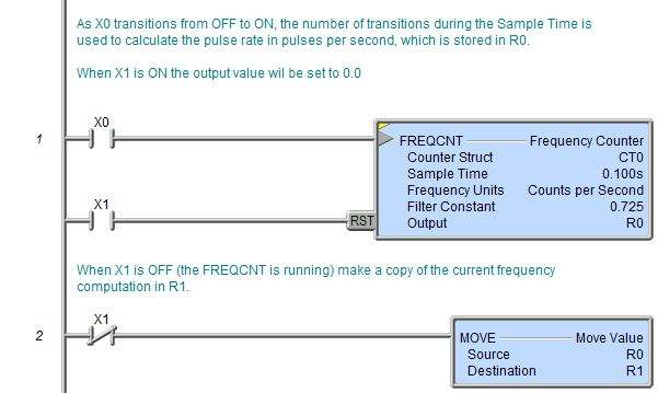
Rung Example: