Topic: DMD0449

Module Configuration for F2-8AD4DA Combo Analog Modules
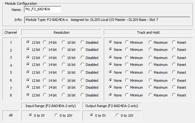
When a Do-more CPU powers up and detects a new F2-8AD4DA-1 or F2-8AD4DA-2 module it will automatically create a new module configuration. Clicking the Edit Config button in the Module Configuration utility will open the following dialog where the default configuration can be changed.
The Module Configuration's Name will become a Device, which will be used in instructions that target this
I/O Module. Be careful to choose a meaningful and unique name. Module
configuration Names follow Nickname Rules![]() Nicknames can be 1 to 16 characters in length and consist of any combination of alphanumeric characters and underscores ('_', 'a-z', 'A-Z', 0-9), no spaces or punctuation marks are allowed, and must begin with a letter or an underscore..
Nicknames can be 1 to 16 characters in length and consist of any combination of alphanumeric characters and underscores ('_', 'a-z', 'A-Z', 0-9), no spaces or punctuation marks are allowed, and must begin with a letter or an underscore..
The output I/O Map for this module contains three additional WY locations that are used as runtime configuration registers. These four sets of values will be written to their mapped WY locations when the Do-more system is powered ON, and each time controller changes modes (PROGRAM -to RUN and RUN -to- PROGRAM). These values can be changed while the controller is in RUN mode by writing to the associated image register locations. These registers locations can be seen in the I/O Mapping section of the System Configuration.
Note: if the F2-8AD4DA module resides in an Ethernet I/O Slave base, the Resolution, Track and Hold, Input Range and Output Range selections will only be written at power-up, and on PROGRAM -to- RUN mode changes; they will NOT be written during RUN -to- PROGRAM mode changes.
Note: if the PLC powers up in PROGRAM mode the Resolution, Track and Hold, Input Range and Output Range selections will not take effect until the PLC first goes into RUN mode. This will cause unexpected channel failure warnings (seen in the I/O System View) for channels that are configured to be disabled. These warnings will go away once the PLC goes into RUN mode.
The Channel Specific Settings are available on individual channels:
The Resolution of each of the eight input channels can be individually disabled or configured for 12, 14, or 16 bit resolution.
The Track and Hold feature for each of the eight inputs can be individually configured for minimum, maximum, no hold, or reset held value.
The All selections affect all of the channels on the module:
The Input Range (F2-8AD4DA-2 Only) of the eight input channels can be collectively set for 0 - 5V or for 0 - 10V range.
The Output Range (F2-8AD4DA-2 Only) of the four output channels can be collectively set to generate output voltage in the 0 - 5V or 0 - 10V range.
Consult the DL205 Analog I/O User Manual for more additional information on how these configuration settings are used by the module.