Topic: DMD0458

Module Configuration for BX-2AD2DA-2B, and BX-4AD2DA-2B Combo Analog Modules
When a Do-more CPU powers up and detects a new BX-2AD2DA-2B or BX-4AD2DA-2B module it will automatically create a module configuration and assign the required I/O mapping using the first 2 or 4 available WX (32-bit signed integer) locations, first 2 available WY (32-bit signed integer) locations, and the first 24 available X (input bit) locations required by the module.
The default configuration has all of the channels enabled in 0-10vdc mode with scaling disabled. Clicking the Edit Config button in the Module Configuration utility will open the following dialog where the default configuration can be changed.
The Global Settings tab for this module sets the following options that apply to the module as a whole, or to all of the channels on the module:
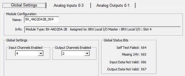
The Module Configuration group:
Name is a name assigned to the module, The default name is the module's part number followed by the slot number where it currently is located. The default name can be changed if required.
Info shows the part number, the number of the controlling I/O Master, and the slot number where the module is located.
The Global Settings group:
Input Channels Enabled selects how many of the module's available input channels will have an input attached. Channels are enabled in order starting with the first channel. Channels that are enabled WITHOUT having a input installed will generate a Broken Transmitter error.
Output Channels Enabled selects how many of the module's available output channels will have an input attached. Channels are enabled in order starting with the first channel.
The Global Status Bits group shows the X bit locations the module uses to indication module-wide errors:
Self Test Failed indicates the module did not pass its power-on self test.
Missing 24V indicates the required external 24 VDC power is not connected.
Input Data Not Valid indicates the proper module configuration was not written to the module at power-up, or that the module lost it's configuration at runtime (probably due to extreme noise), or that the input is out of range.
Output Data Not Valid indicates the proper module configuration was not written to the module at power-up, or that the module lost it's configuration at runtime (probably due to extreme noise).
Input Channel Setup
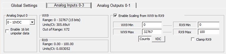
The Analog Inputs 0-1 and Analog Inputs 2-3 (if available) tab sets the following options that are specific to the individual channels:
Analog Input # selects the input voltage range, either 0 - 5V, 0 - 10V, +/- 5V, or +/- 10V.
The default range of values for analog inputs is -32768 to +32767. If one of the unipolar voltage ranges is selected , the default bipolar range setting will yield values of 0 - 32767. Each channel can be optionally configured to use the full range of 65535 counts with the Enable 16 bit Unipolar Mode selection. The one caveat with this selection is that any time you reference the raw value in WX# you must also use the ":U" cast operator to get the correct value.
The WX# group shows the range of values, the Units / Count of the raw input value, and the bit memory location for the Data Out of Range indication.
The RX# group (if automatic scaling is enabled for this channel) shows the Real numeric memory location where the scaled value will be stored in the CPU, the range of potential values and the Units / Count based on the current scale factors.
Enable Scaling from WX# to RX# enables the automatic scaling of the raw input value (32-bit signed integer) to engineering units (32-bit real).
WX# Min / WX# Max the minimum and maximum raw values determined by the Analog Input # selection.
Counts / VDC displays the WX#'s Min and Max values in terms of the range of counts or the voltage range.
RX# Min / RX# Max contains the minimum and maximum values for the engineering units.
Clamp RX# (if enabled) and the calculated scaled value is lower than RX # Min or higher than RX# Max, the specified Min and Max values will be used.
Output Channel Setup
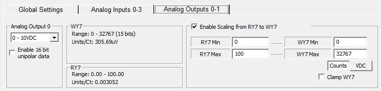
The Analog Outputs 0-1 and Analog Outputs 2-3 (if available) tab sets the following options that are specific to the individual channels:
Analog Output # selects the output voltage range, either 0 - 5V, 0 - 10V, +/- 5V, or +/- 10V.
The default range of values for analog outputs is -32768 to +32767. If one of the unipolar voltage ranges is selected , the default bipolar range setting will yield values of 0 - 32767. Each channel can be optionally configured to use the full range of 65535 counts with the Enable 16 bit Unipolar Mode selection. The one caveat with this selection is that any time you reference the raw value in WX# you must also use the ":U" cast operator to get the correct value.
The WY# group shows the range of values, the Units / Count of the raw output value.
The RY# group (if automatic scaling is enabled for this channel) shows the Real numeric memory location where the engineering unit value is stored in the CPU, the range of potential values and the Units / Count based on the current scale factors.
Enable Scaling from RY# to WY# enables the automatic scaling of the engineering units to raw output value.
RY# Min / RY# Max contains the minimum and maximum values for the engineering units.
WY# Min / WY# Max the minimum and maximum raw values determined by the Analog Output # selection.
Counts / VDC displays the WX#'s Min and Max values in terms of the range of counts or the voltage range.
Clamp WY# (if enabled) and the calculated scaled value is lower than WX # Min or higher than WX# Max, the specified Min and Max values will be used.