Topic: DMD0548

EtherNet/IP Scanner Configuration
Note: EtherNet/IP Scanner support is only available in a BRX CPU with an on-board Ethernet port.
Ethernet-equipped BRX CPUs can configure their on-board Ethernet port or a BX-P-ECOMEX POM to operate as an EtherNet/IP Scanner to process I/O Messaging - also called Implicit - sessions with up to 32 EtherNet/IP Adapters. Each of the sessions can have from 1 to 8 Messages. I/O Message connections to Adapters can be created using EDS (Electronic Data Sheet) files as the source of the required parameters, or created by entering the required parameters manually.
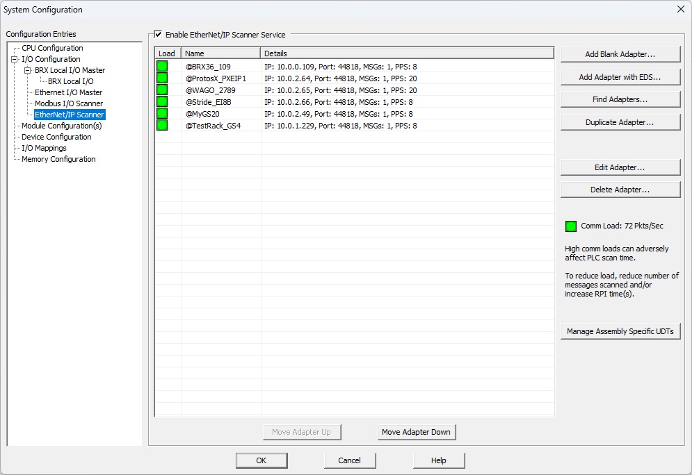
Load column shows each adapter connection's contribution to the cumulative Comm Load.
Name column shows the user-assigned name for the connection to the Adapter.
Details column displays a short summary of the most important details of the connection: the IP address of the Adapter, the Port number used, the number of Messages configured, and the packet rate for this connection.
Enable EtherNet/IP Scanner to create I/O Messaging (Implicit) connections to Adapters, and enable processing of the currently configured Adapter connections.
Add Blank Adapter... will open the EtherNet/IP Adapter Settings editor with all of the fields set to their default values so that a connection to a new Adapter can be created. No EDS file will be used so all of the required parameters for the Message will need to be entered manually.
Add Adapter with EDS... will open the EtherNet/IP Adapter Settings editor and prompt for the EDS file to use, so that a connection to a new Adapter can be created using the selected EDS file.
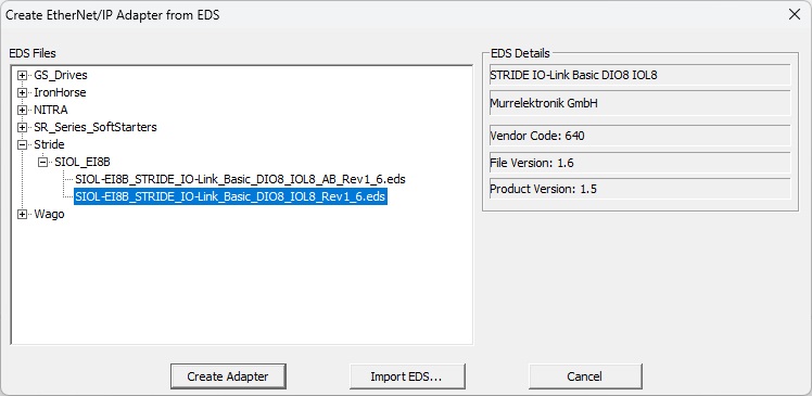
Details from the highlighted EDS file will be displayed in the EDS Details pane on the right.
Clicking Create Adapter will open the EtherNet/IP Adapter Settings editor already populated with the information from the highlighted EDS file.
Clicking Import EDS... will open an Explorer dialog to <Public Documents>\Do-more\Profiles\EDS folder so that you can make new folders and copy additional EDS files into those folders.
Clicking Find Adapters... will cause the BRX CPU run a query for any EtherNet/IP adapters that are currently available on the network. This query will collect responses for 5 seconds then populate a list with adapters that are available but are NOT already being used by the EtherNet/IP Scanner. If the highlighted adapter in the list has an associated EDS file, pertinent details from the adapter's EDS file will be displayed in the pane on the right.
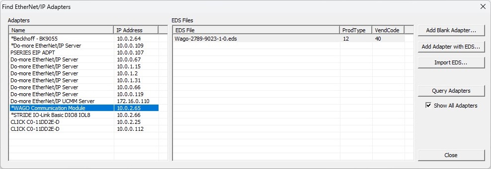
Clicking Add Blank Adapter... will open the EtherNet/IP Adapter Settings dialog with the IP Address of the highlighted Adapter populated. You will need only to enter a name for the Adapter and manually create the I/O message.
Clicking Add Adapter with EDS... will open the EtherNet/IP Adapter Settings dialog with the IP Address of the highlighted Adapter populated . You will need only to enter a name for the Adapter, select the I/O Message from among those defined in the EDS file, and provide local storage locations as required by those messages.
Clicking Import EDS... will open an Explorer dialog to <Public Documents>\Do-more\Profiles\EDS folder so that you can make new EDS file folders and copy additional EDS files into those folders.
Clicking Query Adapters will have the BRX CPU run the query for EtherNet/IP adapters on the network again; this query takes 5 seconds.
Enabling the Show All Adapters will populate the Adapters list with the all of the adapters found during the last query operation, even those that are already being using by the Scanner.
Duplicate Adapter will make an exact copy of the currently highlighted connection and open that new connection in the Adapter Settings editor. This can be quite handy when there are connections to multiple adapters with similar messaging; you need only change the Device Name, IP Address, and local storage for the data as required.
Edit Adapter... will open the highlighted entry in the EtherNet/IP Adapter Settings editor.
Delete Adapter... will remove the highlighted Adapter connection along with the I/O Message from the current Scanner configuration.
Comm Load provides a visual cue to the cumulative level of network traffic that is being generated by all of the EtherNet/IP Scanner devices currently configured. As the Comm Load increases from Green -to- Yellow -to - Red, the impact on the Adapter, and impact on other processes in the CPU will increase as well. For example, the CPU scan time will go up meaning the responsiveness of the Ethernet port to other connections, (Do-more Designer, Ethernet Remote I/O, etc.) will go down. The Comm Load can be lowered by reducing the number of messages being generated by the current Adapter connections, or by increasing the RPI Time![]() The RPI value determines how often the input data will be sent back to the Scanner from the Adapter, and how often the Scanner will be sending output data to the Adapter. The smaller the value configured in this field, the more resource intensive it will be for both the Scanner and the Adapter. (requested packet interval) of the Messages in those connections.
The RPI value determines how often the input data will be sent back to the Scanner from the Adapter, and how often the Scanner will be sending output data to the Adapter. The smaller the value configured in this field, the more resource intensive it will be for both the Scanner and the Adapter. (requested packet interval) of the Messages in those connections.
Manage Assembly Specific UDTs allows UDTs that were created as part of the Local Address selection for an I/O Message to be edited and / or deleted.
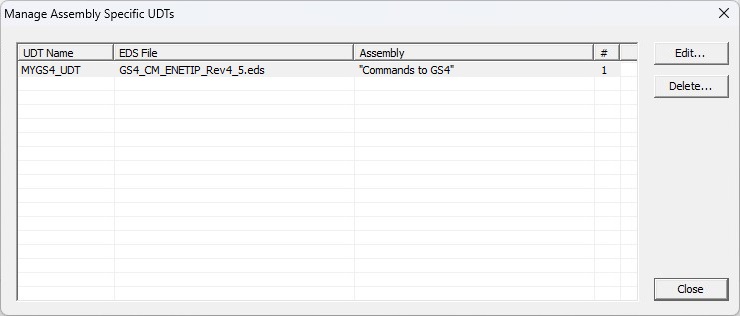
UDT Name is the User-assigned name for the UDT.
EDS File is the name of the EDS file that contains the Assembly used to create the UDT.
# is the number of instances of structures that have been created using the UDT.
Click the Edit... button to open the highlighted UDT in the same editor that was used to create the UDT.
The Delete... button will be enabled if the # of instances of structures using this UDT is 0. To delete a UDT that's being used ( the # is non-zero ), you must first remove the structures using the UDT.
Each time the Move Device Up & Moved Device Down buttons are clicked, the currently highlighted Adapter connection will be repositioned one row toward the top or toward the bottom respectively of the list.
The EtherNet/IP Adapter Settings editor is used to create an Scanner connection to an I/O Messaging (Implicit) Adapter and then configure the Message(s) for that Adapter.
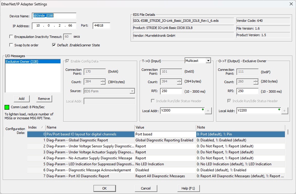
Device Name is the user-assigned name for the Adapter. This is also the name of the structure that is automatically created for each Adapter.
IP Address is the TCP/IP address of the Adapter.
Port (default 44818) is the IP port number for the connection to use, the default value of 44818 is the traditional port number for I/O Messaging (Implicit) connections.
Enable Encapsulation Inactivity Timeout to have the Scanner close the session for this Adapter the specified number of seconds of inactivity.
Enable Swap Byte Order to have the Scanner swap the byte order of the data coming from the Adapter (T->O) or being sent to the Adapter (O->T). This option does not affect the byte order of the configuration data in EDS Form, but it will affect the configuration data if it is one of the Word Array types.
The Scanner will use the Default .EnableScanner State to determine whether the connection to the specified Adapter will be enabled. This selection is used each time the CPU powers up, or a programming change is made that requires an update to the System Configuration.
If the Adapter was created with an EDS file, the EDS File Detailsgroup is automatically displayed with pertinent information from that EDS file.
The I/O Messages group contains the parameters that define the optional Config Data, T->O (Input), and O->T (Output) blocks for each I/O Message.
A User Defined message will have no predefined parameter values.
An Exclusive Owner type connection has an O->T (Output) Byte Count value greater than 0. This is a Class 0 or 1 connection to an Output connection point that allows the Scanner to send Data to the Target (O->T). The Target can send Input Data to the Scanner (T->O). The Target can only accept one connection to the specified Output connection point. If the Input Data length in this connection is zero, then a 'heartbeat' connection point is used.
An Input-Only type connection will have a T->O (Input ) Byte Count value of 0. This is a Class 0 or 1 connection to an Input connection point that allows the Target to send Data to the Scanner (T->O). The Scanner sends no Output Data to the Target, but rather maintains the connection using a 'heartbeat' connection.
The Listen-Only type connection is similar to the Input-Only connection, but this connection is dependent upon the existence of some other non-Listen-Only connection (Exclusive Owner or Input-Only) for its own existence. If the Exclusive Owner / Input-Only connection closes, the Listen-Only connection will also close or timeout. A Target can only open a Listen-Only connection while there is an existing Exclusive Owner or Input-Only connection.
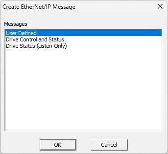
The Add button will create a new Message.
If the Adapter was created from an EDS file, the Create Message dialog will contain a list of the Messages defined in the EDS file. Refer to the two examples below:
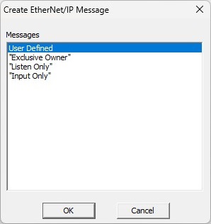
If the Adapter was NOT created with an EDS file, or if User Defined is selected, entries numbered MSG1 - MSG8 will be added to the I/O Messages list each time a message is added. Note: not all Adapters can accept multiple Messages per session.
The Remove button will delete the highlighted Messages.
Comm Load provides a visual cue to the level of network traffic that will be generated for this Adapter by the currently defined I/O Messages. The Comm Load can be lowered by reducing the number of I/O Messages or by increasing the RPI (requested packet interval) of the Message.
Enable the optional Config Data group if the Message includes Configuration Data. Note: If an EDS file was used to create the Adapter, and the selected Message has a Connection Point for the Config Data, the EDS file's information will be used for the Connection Point, Count, and Source, and cannot be changed.
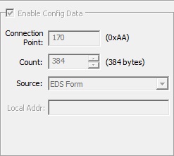
Connection Point is the Connection Point parameter for the desired configuration data block of the Adapter. This value is specific for the Adapter and is determined from the manufacturer’s documentation of that device. If the EDS file's configuration is list of possible connection points - instead of a single constant value - the possible selections will be available in a drop-down. If the Adapter connection was NOT created using an EDS file, this can be any constant value or any readable numeric location.
Count specifies how many contiguous Bytes of Config Data are written by the Scanner in this Message. The values for the configuration data is entered in the Configuration Data section below.
Source selects the data type of the Config Data. If an EDS file was used to create the Message, the default will be EDS Form and cannot be changed. If the Adapter connection was NOT created using an EDS file, this can be one of the following selections:
Select Local Address then specif y the beginning memory location in the CPU where the Config Data will be read from. The values in these locations will be retrieved each time the Scanner establishes the connection to this Adapter. Note: pressing F9 while the field has focus will open the Element Picker.
Select Unsigned Byte Array if the Config Data consists of Unsigned Byte values.
Select Signed Byte Array if the Config Data consists of Signed Byte values.
Select Hex Byte Array if the Config Data consists of Hexadecimal Byte values.
Select Unsigned Word Array if the Config Data consists of Unsigned Word values (2 Bytes per value).
Select Signed Word Array if the Config Data consists of Signed Word values (2 Bytes per value).
Select Hex Word Array if the Config Data consists of Hexadecimal Word values (2 Bytes per value).
The Configuration Data group at the bottom of the dialog allows editing of the individual items of the Config Data.
If the Adapter was created using an EDS file, and the selected Message has a Connection Point for the Config Data, the EDS file's Config Data information will be displayed.
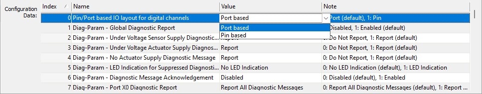
Index is the Byte or Word offset into the Config Data block.
Name is the Field name read from the EDS file.
Value is the selected value for the field read from the EDS file. Click on the current value to see a list of the available optional values, then click one of the displayed values to select it.
Note is text read from the EDS file that contains a short description of the field and / or the optional values for that field. Note: If the text is too long to be displayed, hovering the mouse cursor over the Note field will display all of the text in a popup .
If the Adapter was created manually - not using an EDS file - the Configuration Data values for each item will need to be entered manually:
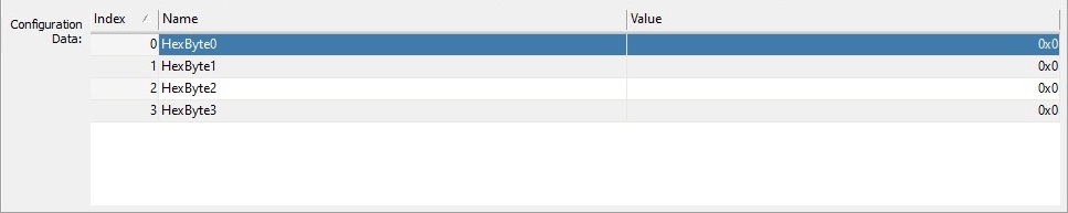
Index is the Byte or Word offset into the Config Data block.
Name will be in the form Signed Byte X, Signed Word X, etc. depending on which data type was selected for the Config Data.
Value is for each Byte or Word is manually entered in the field.
The T->O (Input) group defines the data being read from the BRX CPU by the EtherNet/IP Scanner. Note: If an EDS file was used to create the Adapter, and the selected Message has a Connection Point for the Input Data, the EDS file's information will be used for the Connection Point, Count, and the Run / Idle Status Header option, and cannot be changed.
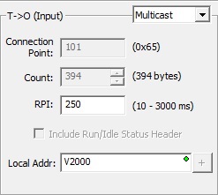
Select Multicast or Unicast. Some Adapters can be configured to either Multicast their input data on the network or Unicast their input data back only to the Scanner (originator). Some devices only support multicasting of input data. In situations where the Adapter supports both, and there are multiple devices consuming this data, then it is more efficient to use Multicast.
Connection Point is the Connection Point parameter for the desired input data block of the Adapter. This value is specific for the Adapter and is determined from the manufacturer’s documentation of that device. If the EDS file's configuration is list of possible connection points - instead of a single constant value - the possible selections will be available in a drop-down. If the Adapter connection was NOT created using an EDS file, this can be any constant value or any readable numeric location.
Count is number of contiguous Bytes of data read by the Scanner in this Message. This can be any positive integer value or any readable numeric location.
RPI is the Requested Packet Interval (in ms) for this connection. The RPI value determines how often the input data will be sent back to the Scanner from the Adapter. The smaller the value configured in this field, the more resource intensive it will be for both the Scanner and the Adapter. This can be any positive integer value between 10 and 1,000,000 milliseconds, or any readable numeric location containing a value in that range.
If Include Run / Idle Status Header is enabled, 4 additional bytes are added to the message to contain the Run / Idle Header status information.
Local Addr selects the beginning of an existing memory location in the CPU where the data to send to the Scanner is stored. Note: pressing F9 while the field has focus will open the Element Picker. If the Adapter was built from an EDS, and the Connection Point selected requires less than 255 bytes of local data, the Add UDT (Square with the + sign) will be enabled. Clicking that button will open the Create Connection Point Data dialog that either creates a new data block of the correct type, or builds a new UDT with fields from the specified assembly and a structure from that UDT. See the section below for details on that dialog's options.
The O->T (Output) group defines the data being written from the EtherNet/IP Scanner to the BRX CPU. The name of the I/O Message selected from the EDS file will be displayed in the header. Note: If an EDS file was used to create the Adapter, and the selected Message has a Connection Point for the Output Data, the EDS file's information will be used for the Connection Point, Byte Count, and the Run / Idle Status Header option, and cannot be changed.
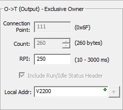
Connection Point is the Connection Point parameter for the desired output data block of the Adapter. This value is specific for the Adapter and is determined from the manufacturer’s documentation of that device. If the EDS file's configuration is list of possible connection points - instead of a single constant value - the possible selections will be available in a drop-down. If the Adapter connection was NOT created using an EDS file, this can be any constant value or any readable numeric location.
Count is number of contiguous Bytes of data written from the Scanner in this Message. This can be any positive integer value or any readable numeric location.
RPI is the Requested Packet Interval (in ms) for this connection. The RPI value determines how often the output data will be sent from the CPU to the Adapter. The smaller the value configured in this field, the more resource intensive it will be for both the Scanner and the Adapter. This can be any positive integer value between 10 and 1,000,000 milliseconds, or any readable numeric location containing a value in that range.
If Include Run / Idle Status Header is enabled, 4 additional bytes are added to the message to contain the Run / Idle Header status information.
Local Addr selects the beginning of an existing memory location in the CPU where the data from the Scanner will be stored. Note: pressing F9 while the field has focus will open the Element Picker. If the Adapter was built from an EDS, and the Connection Point selected requires less than 255 bytes of local data, the Add UDT (Square with the + sign) will be enabled. Clicking that button will open the Create Connection Point Data dialog that creates either a new data block of the correct type, or a new UDT with fields from the specified assembly and a structure from that UDT. See the section below for details on that dialog's options.
If the Adapter was built from an EDS, and the Connection Point selected requires less than 255 bytes of local data, the Add UDT (Square with the + sign) will be enabled. Clicking that button will open the Create Connection Point Data dialog that either creates an new data block of the correct type, or builds a new UDT with fields from the specified assembly and a structure from that UDT.
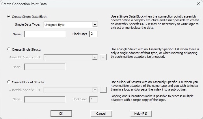
Select Create Simple Data Block to create an array of the proper data type and length. This is the proper selection when the assembly doesn't specify mixed data types, that is, all of the data are the same type. However, if the array's data type doesn't lend itself to proper type in the CPU - for example, if the array type is Unsigned Bytes, but the actual value is a 32-bit Real value that consumes 4 successive bytes in the array - you will need to use additional ladder logic to make those conversions. Enter a Name for the new Data Block; the length will be prefilled with the value from the EDS file.
Select Create a Single Struct to create a UDT and a structure from that UDT that has the appropriate fields and lengths to match the assembly's layout of the data. This is the proper selection if there is only a single Adapter that will be using the assembly from this EDS file. Select the appropriate Assembly-specific UDT and then enter a Name for the structure using that UDT.
Select Create a Block of Structs to create a UDT and a data block of structure from that UDT that has the appropriate fields and lengths to match the assembly's layout of the data. This is the proper selection if there are multiple Adapters that will be using this EDS file. Select the appropriate Assembly-specific UDT then enter a Name for the Data Block that will contain the structures built using that UDT and the number of structures in the data block.
Clicking the Add UDT (Square with the + sign) button at the right of either structure field will open the Create Assembly-Specific UDT from EDS dialog that will allow you to build a UDT from the selected parameter fields of the Assembly.
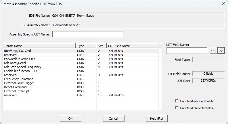
The EDS File Name and EDS Assembly Name show the EDS file and Assembly that is the source of the parameters.
Assembly-Specfifc UDT Name is a 16-character name for the UDT that will be created.
Values in the Param Name, Type, and Sizecolumns come from the Assembly that was selected from the EDS file. The UDT Field Name is initially empty unless the parameter is either a Bit field NOT DWord aligned. If the value is either <Multi-Bit>, <Misaligned Byte>, or <Misaligned Word>, and that field is selected to be part of the UDT, the misalignment must be accounted for.
After highlighting a parameter, enter a valid 16-character name for that field inUDT Field Name. Field Type will show the data type that will be used in the UDT for that parameter.
UDT Field Count and UDT Size keep a running total of the number of fields and the UDT structure size as fields are being added to the UDT. An assembly-specific UDT has a maximum of 255 fields and a maximum size of 64 DWords.
Enabling the Handle Misaligned Fields option for an unaligned parameter will add memory to the end of the UDT to make space for a properly aligned value. The UDT Size will increase appropriately as memory is added.
Enable the Handle Multi-Bit Fields option to add memory to the end of the UDT to make space to pack the Bits. The UDT Size will increase appropriately as memory is added.
Structure Fields
Each time a new Adapter is created, an associated data structure will be automatically created using the same name as the Adapter. The fields of this structure care used to provide runtime status and control of the Scanner's connection to the Adapter.
$<EIP Adapter name>
Each Implicit Adapter structure contains the following fields:
.EnableScanner is a Bit that indicates the current State of the Scanner connection to this Adapter; ON means the connection is enabled, OFF means disabled.
.TCPConnected is a Bit that will be ON if the TCP session is currently connected to the Adapter. OFF doesn't necessarily indicate a failed state; it could mean the scanner only uses TCP to establish the connection but then only uses UDP to perform the read and write operations.
.Error is a Bit that will be ON if the TCP connection is not functional (typically due to a Timeout).
.RunIdle is a Bit that reflects the Run / Idle state from the T -> O (Input) header.
.EnableMSG1 through .EnableMSG8 are Bits that will be ON if that MSG has been enabled for this Adapter. Turning this Bit OFF will prevent this MSG from being processed.
.EnableMSG is an Unsigned Byte that contains a Bit for each of the 8 possible MSGs for this Adapter; the respective Bit location within the Byte will ON if the MSG is enabled. Turning a Bit OFF will prevent the corresponding MSG from being processed.
.MSGStatus is an Unsigned Byte that contains a Bit for each of the 8 possible MSGs for this Adapter; the respective Bit location within the Byte will ON if that MSG is communicating successfully.
.MSGError is an Unsigned Byte that contains a Bit for each of the 8 possible MSGs for this Adapter; the respective Bit location within the Byte will ON if that MSG is NOT communicating successfully.
.GenStatusCode is an Unsigned Byte that contains the last General Status Code value reported to the Scanner from this Adapter.
.ExtStatusCode is an Unsigned Word that contains the last Extended Status Code value reported to the Scanner from this Adapter.
.ExtStatusInfo1 is an Unsigned Word that contains the last Extended Status Info 1 value reported to the Scanner from this Adapter.
.ExtStatusInfo2 is an Unsigned Word that contains the last Extended Status Info 2 value reported to the Scanner from this Adapter.
.LastError is the last error code reported to the Scanner.
.XferCount is an Unsigned Word that contains running count of the successful T -> O (Input) and O -> T (Output) data transfers.
.ErrorCount is an Unsigned Word that contains a running count of the unsuccessful T -> O (Input) and O -> T (Output) data transfers.
.VendorID (read-only) is an Unsigned Word that contains the Vendor ID read from the Adapter, or from the EDS file (if applicable).
.AdapterName (.MaxLen = 32) is a String of up to 32 characters that contains the name of the Adapter read from the EDS file (if applicable).
See Also:
EtherNet/IP Server / Adapter Configuration
Ethernet Remote I/O Master Configuration
Modbus I/O Scanner Configuration
EtherNet/IP Scanner Configuration
Related Topics:
EtherNet/IP Server / Adapter Configuration
EIPMSG - Send EtherNet IP Message (explicit)