
Do-more
FAQ0001
06-Sep-2012
Q: Will it be possible to program the older DL-PLCs with Do-more
Designer?
A: No, only the DM1 and DM1E are currently programmable
with Do-more Designer.
Originally we intended to allow the programming of the older DL-PLCs, but as the design developed we realized by moving to strong data types and structures we were fundamentally changing the way we did some critical things which moved us further and further away from maintaining compatibility with DL-PLCs. So the decision was made to build the best controller and software we could instead of trying to maintain compatibility with DL-PLCs.
Do-more FAQ0002
06-Sep-2012
Q: Will there be a DirectSOFT6 for the older DL-PLCs?
A: Yes. After Do-more is rolled out, there are plans to do
another major release of DirectSOFT for the older DL-PLCs.
Do-more FAQ0003
06-Sep-2012
Q: Why are there no ISG (Initial Stage) instructions?
A: In the DL-PLCs
there is no program modularity and users are therefore forced to
modularize their programs with stages and therefore multiple ISGs were
needed. By contrast, Do-more PLCs are designed to be modular (Task
& Program code blocks) with Program code blocks supporting stages.
Since each Program code block can have its own block of 128 stages
running independently and the very first stage is the initial one, then
the ISG instruction is not needed. This simplifies stages and encourages
a better programming practice of having a single well-defined entry
point for a sequence.
If multiple parallel sequences are needed
in a single Program code block, use the SGDIVRG (Jump to Mulitple
Stages) instruction in the first stage or simply set the other stages
from the first stage.
In a Do-more PLC, Program code blocks should be thought of as individual
sequencing operations and each sequencing operation should have one
starting point.
Do-more FAQ0004
06-Sep-2012
Q: Does the Do-more CPU have more memory than the DL260?
A: Yes.
| MEMORY ELEMENT | DL260 | DM1/DM1E |
| Data | 34 Kbytes | 256 Kbytes |
| Program | 15,872 instruction words | 65,536 instruction words |
Do-more FAQ0005
06-Sep-2012
Q: Are the more complex high-level instructions (e.g.
DLRX/DLWX/MRX/MWX and MATH) more efficient than IBoxes in the DL260?
A: Except for MATH, yes. IBoxes are just macros whereas all the
complex instructions in Do-more are native and all of the interlocking
to the instruction and device driver are internal. But as for MATH it
is still much faster in the Do-more (e.g. integer MATH in Do-more is
nearly as fast as the simple contact/coil instructions!).
Do-more
FAQ0006
06-Sep-2012
Q: What is the typical scantime of a Do-more PLC?
A: Like all things PLC, this is a wide open question. The minimum
scan time is about 150 µs. Certain modules that tax the DL205 backplane
a bit (e.g. CTRIO/CTRIO2) will raise that. With a single CTRIO2 in the
base the minimum scan is about 258 µs. Boolean instructions, math and
boolean stack operations, and most integer math operations are all very
fast, generally running at about 50 ns per instruction, or 50 µs per K
of logic.
More complex instructions, of course, will increase the scan
accordingly. Given typical PLC programming the typical scantime will
probably be submillisecond to a few milliseconds. So for most users,
speed won't be an issue, especially if Stages and modularity mechanisms
are utilized as intended.
Do-more
FAQ0007
17-Jul-2024
Q: Will interrupts be supported?
A: They were not supported in the initial release, but were added
22-Feb-2017 in Do-more Designer v2.0.2.
Do-more
FAQ0008
06-Sep-2012
Q: Is the serial communication half or full duplex?
A: Full duplex. It is possible to fill the Do-more base
with SERIO-4 modules and run Do-more Server, Modbus RTU Server,
Modbus RTU Client, K-Sequence Server, or even custom protocols on every
port simultaneously.
Do-more FAQ0009
06-Sep-2012
Q: How many Modbus TCP clients (masters) can talk to the DM1E
internal Ethernet port?
A: The DM1E can maintain 16 connections as a Modbus TCP Server
(slave). If the 17th master attempts a TCP connection, the DM1E would
simply reject the connection request.
Do-more
FAQ0010
19-Sep-2012
Q: Is Do-more Designer software free?
A: Yes, and it will always be free!
Do-more
FAQ0011
01-Oct-2018
Q: Is there any type of utility (like DNLoader) that the
end customer can use to update the Do-more PLC without needing a copy
of Do-more Designer and without knowing the PLC password?
A: Do-more Designer v1.3 has a utility called DMLoader (Do-more
Loader). It can be run from within Do-more Designer, or you can download
and install it from http://www.dmloader.com.
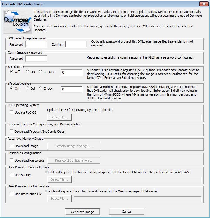
DMLoader can download the image of a Do-more PLC into another Do-more PLC. Hence, Do-more PLCs can be programmed without the need to know the details of Do-more Designer.
The first half of this utility is the Image Generator, which runs within Do-more Designer. Easily replicate an online PLC from within Desinger via the File --> Export --> Generate DMLoader Image menu. Various options include password protecting the image file itself, downloading the PLC firmware as part of the image download, and customize the look of the DMLoader.EXE utility with your logo and your detailed instructions.
Once the DMLoader image file (.DLI) is generated, anyone can install DMLoader.EXE utility from the Internet and upgrade their Do-more PLC if they have this DLI file, without the need of understanding Do-more Designer or without the original Do-more Designer project file.
Do-more
FAQ0012
19-Sep-2012
Q: What kind of program security does Do-more have?
A: Each code block in a Do-more PLC can be individually configured
as Full Access or Locked. When Locked, the block's logic is not viewable
without a password. But even after entering a password, it remains
viewable only for that one Do-more Designer session.
Do-more FAQ0013
14-Apr-2016
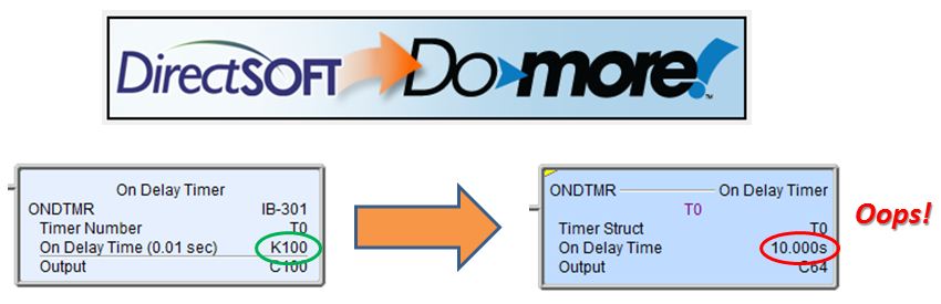
Q: Is there a utility that will translate DL230, DL240, DL250(-1)
and DL260 projects into Do-more Designer projects?
A: Yes. As of Do-more Designer v1.3.1.1 (03-Apr-2014) a
DirectLOGIC Migration Utility was added to help migrate existing
DirectSOFT projects to Do-more Designer projects.
Do-more
FAQ0014
<REMOVED>
Do-more
FAQ0015
17-May-2021
Q: Will HMIs or PCs that support protocols that worked with the
older DL-PLCs also work with the Do-more PLCs?
A: Yes, using either Modbus or K-sequence drivers. In both cases
the memory that will be utilized is called "guest memory" in the
Do-more.
If using a Modbus
protocol with the Do-more PLC as the server (slave), then the memory
that will be read from and written to is:
MC - Modbus Coils
MI - Modbus Inputs
MIR - Modbus Input Registers
MHR - Modbus Holding Registers
If using a K-sequence
protocol with the Do-more PLC as the server (slave), then the memory
that will be read from and written to is:
DLC - Direct Logic Coils (with
octal addressing)
DLX - Direct Logic Inputs (with
octal addressing)
DLY - Direct Logic Outputs (with
octal addressing)
DLV - Direct Logic V-memory
(with octal addressing)
NOTE: The default sizes of all these guest memories can be increased as needed by using PLC --> Memory Configuration.
Do-more
FAQ0016
06-Sep-2012
Q: What are the highest values for timers and counters?
A: Timers are all millisecond resolution using 32-bit signed numbers
(-2,147,483,648 to +2,147,438,647), thus millisecond resolution for more
than 24 days. Counters are also 32-bit signed numbers, hence you can
count up to 2,147,438,647 or down to -2,147,438,648.
Do-more
FAQ0017
06-Sep-2012
Q: Are the familiar DL-PLC memory types supported in Do-more PLCs?
A: Most DL memory types also exist in a Do-more PLC. X,
Y, and C are Discrete Input, Discrete Output, and
Internal Bits. However, Do-more element blocks are numbered in decimal,
not octal. So, yes, there is an X8 (and an X9).
V memory in Do-more is a 16-bit unsigned integer, with a range of
0-65,535. Instead of storing 32-bit IEEE real numbers in V memory, or
32-bit signed integers in V memory, or 16-bit signed integers in V
memory, we created three additional memory blocks, R, D
and N, respectively. Each
element in the R block is a 32-bit real number. Each element in the D
block is a 32-bit signed 2's complement integer number. Each element in
the N block is a 16-bit signed 2's complement integer number. All of
these blocks also have decimal IDs.
Use V memory when you need integer values 0-65535.
Use N memory when you need signed integer values -32,768 to +32,767
Use D memory when you need signed integer values -2,147,483,648
to +2,147,438,647
Use R memory when you need real (floating point) values.
The good news is that the MATH instruction can properly handle mixing
and matching any of these data types in Do-more. For instance, this is a
valid MATH expression:
(ROUND(SQRT(R0)) + V8) * D3.
Timer/Counter bits and accumulator values are now part of Timer
and Counter structures. T0 represents the entire Timer structure for
timer T0. Within these structures are various "dot fields," e.g. .Done
.Acc .Reset. To know when Timer #0 is done, enter T0.Done. To look at
Counter #9's accumulator, enter CT9.Acc. This means that V0 is User V
memory, not T0's accumulator like in the DL-PLCs. Also, all of the .Acc
accumulators are 32-bit signed integers with a range of -2,147,438,648
to +2,147,438,647.
Do-more
FAQ0018
17-May-2021
Q: What is the instruction list for Do-more?
A: For a complete list of Do-more instructions, install Do-more
Designer (free!), then go to the Help file and click on Instruction Set.
Do-more
FAQ0019
06-Sep-2012
Q: What do the PUBLISH and SUBSCRIB instructions do?
A: These instructions could possibly be needed when an external
system is providing data or the Do-more PLC is providing data to an
external system and the data types do not exactly match. These
instructions let you move/convert/align the data to Do-more memory
locations. Both of these are table instructions, where for each row in
the table instruction, you enter a source, destination and number of
elements and the options for converting it.
Those options are:
The way it was envisioned was to stick one or more SUBSCRIB instructions in the system task $TopOfScan, and one or more PUBLISH instructions at the system task $BottomOfScan, whose sole purpose is to move/convert data to/from 'public' memory and from/to 'internal' memory. Clean and well-bounded.
Do-more FAQ0020
06-Sep-2012
Q: Is there an OROUT instruction (or equivalent) so that an output
can be controlled from more than one ladder rung?
A: There is no OROUT instruction or an equivalent. However the
functionality of an OROUT can be implemented by using the system block
$TopOfScan and an RST of the output there. Then elsewhere in the program
use SET of that same output.
Do-more FAQ0021
06-Sep-2012
Q: The XRef (cross reference) only shows addresses. Can it show rung
numbers instead?
A: The address that is shown is a hotlink to the instruction that it
is used in. Rung numbers map to multiple instructions. Clicking on the
link will jump to the rung and the block cursor will be
overtop of the exact instruction. Once there, the rung number is
seen in the margin. However, in a future version of Do-more Designer we
are considering keeping the link to be addressed-based but the display
you actually see is the rung number.
Do-more FAQ0022
06-Sep-2012
Q: How can I clear a string (Short String (SS) or StringLong (SL))?
A: Use the STRCLEAR instruction.
Do-more FAQ0023
06-Sep-2012
Q: What is the functional equivalent to a DirectLOGIC LD (Load)
instruction?
A: Use the INIT or MOVE instruction.
Do-more
FAQ0024
<REMOVED>
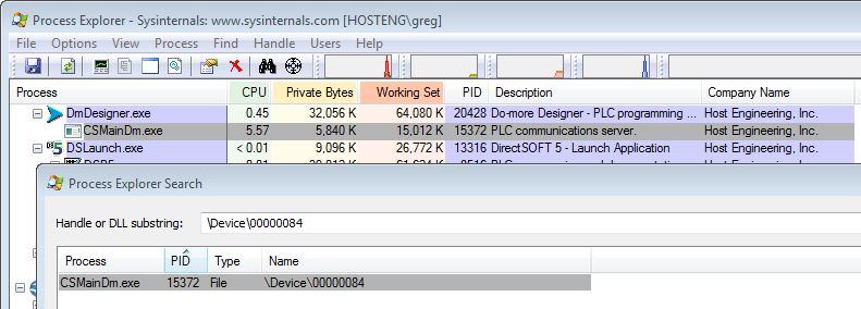
(1) Problems using the USB POM
(BX-P-USB-B) on BRX PLC
This usually manifests itself by connecting only once, but when you try to reconnect any number of subsequent times, it fails. The error message is usually, "Error reading system config from PLC, perhaps due to old PLC firmware."

This issue, we believe, was due to a problem not accounted for in the booter of the BRX PLC.
This was fixed with v1.0.9 of the Booter
released 19-Jan-2021.
(2) Problems using the built-in
USB port on the H2-DM1/E PLC
The most common cause of this issue is a program that comes preloaded on Dell PCs called "Dell Stage." This program grabs the USB port of your PC and thus makes it unusable for Do-more Designer. You must close Dell Stage and particularly the weather widget before your USB port will be freed up to work.

| H2-DM1E |
|||||||||||||||
| PROTOCOL | BUILT-IN PORTS | H2-SERIO / H2-SERIO-4 |
H2-ECOM100 |
||||||||||||
| Ethernet |
Serial |
USB |
Client
(Master) |
Server
(Slave) |
Client
(Master) |
Server
(Slave) |
Client
(Master) |
Server
(Slave) |
|||||||
| Instruction |
Config |
Instruction |
Config |
Instruction |
Config |
Instruction |
Config |
Instruction |
Config |
Instruction |
Config |
||||
| Do-more
Protocol |
X |
X |
X |
None
(1) |
(2) |
None
(1) |
Enable
Do-more Protocol |
None
(1) |
None
(13) |
||||||
| Ethernet
I/O |
X |
Any |
Enable
Ethernet I/O Master |
||||||||||||
| Peerlink |
X |
Use
PEERLINK instruction (3)(14) |
Configure
Peerlink using web
interface (3)(13)(15) |
||||||||||||
| Modbus
TCP |
X |
MRX, MWX |
Modbus TCP Client device
exists by default (4) |
None
(5) |
Modbus TCP Server device
enabled by default (6) |
DLRX,
DLWX
(16) |
Configure
Peer-to-peer Table Entry (Modbus
TCP) in NetEdit |
None
(9)(16) |
None |
||||||
| Modbus
I/O Scanner |
|||||||||||||||
| Do-more
Peer-to-Peer
(7) |
X |
RX, WX |
Do-more Peer-to-Peer Client device
exists
by default (8) |
None
(1) |
Do-more Peer-to-Peer Server
exists by default (8) |
||||||||||
| DirectLOGIC
RX/WX |
X |
DLRX, DLWX |
DirectLOGIC Client device
exists by default (8) |
None
(9) |
DirectLOGIC Server device
exists by default (8) |
DLRX, DLWX |
Configure
Peer-to-peer Table (ECOM)
in NetEdit |
None
(9) |
None |
||||||
| MQTT
(IoT) |
|||||||||||||||
| DMX512 |
|||||||||||||||
| HTTP |
|||||||||||||||
| FTP | |||||||||||||||
| EtherNet/IP
Explicit (7) |
X |
EIPMSG |
EIP Client device exists by
default (4) |
None
(10) |
Enable
EIP Server/Adapter &
define blocks |
||||||||||
| EtherNet/IP
Implicit (17) |
X |
None
(10) |
Enable
EIP Server/Adapter &
define blocks |
||||||||||||
| K-seq |
X |
X |
None
(9) |
Enable
K-Sequence Server |
None
(9) |
Enable
K-Sequence Server |
None
(9) |
None |
|||||||
| Modbus
RTU |
X |
MRX, MWX |
Enable
Modbus RTU Client |
None
(5) |
Enable
Modbus RTU Server |
MRX, MWX |
Enable
Modbus RTU Client |
None
(5) |
Enable
Modbus RTU Server |
||||||
| SMTP
(Email) |
X |
EMAIL |
Create
SMTP Client (Email)
device |
||||||||||||
| SNTP
(Time) |
X |
NETTIME |
None |
||||||||||||
| Do-more
TimeSync |
X |
None |
Select
Client or Alternate |
None |
Select
Server or Alternate |
||||||||||
| Custom
UDP |
X |
PACKETIN, PACKETOUT (11) |
Create
UDP Connection device |
PACKETIN, PACKOUT (11) |
Create
UDP Connection device |
||||||||||
| Custom
TCP |
X |
OPENTCP, STREAMIN, STREAMOUT (12) |
Create
TCP Client device |
TCPLISTEN, STREAMIN, STREAMOUT (12) |
Create
TCP Server device |
||||||||||
| Custom Serial (e.g. ASCII) |
X |
STREAMIN, STREAMOUT (12) |
Enable
Program Control |
STREAMIN, STREAMOUT (12) |
Enable
Program Control |
STREAMIN, STREAMOUT (12) |
Enable
Program Control |
STREAMIN, STREAMOUT (12) |
Enable
Program Control |
||||||
| T1HDM1E |
|||||||
| PROTOCOL |
BUILT-IN
PORTS |
||||||
| Ethernet | Serial |
USB | Client (Master) | Server (Slave) | |||
| Instruction |
Config |
Instruction |
Config |
||||
| Do-more
Protocol |
X |
X |
X |
None
(1) |
(2) |
||
| Ethernet
I/O |
X |
Any |
Enable
Ethernet I/O Master |
||||
| Peerlink |
X |
Use
PEERLINK instruction (3)(13) |
|||||
| Modbus
TCP |
X |
MRX,
MWX |
Modbus TCP Client device
exists by default (4) |
None
(5) |
Modbus TCP Server device
enabled by default (6) |
||
| Modbus
I/O Scanner |
|||||||
| Do-more
Peer-to-Peer
(7) |
X |
RX,
WX |
Do-more Peer-to-Peer Client
device exists by default (8) |
None
(1) |
Do-more Peer-to-Peer Server
exists by default (8) |
||
| DirectLOGIC
RX/WX |
X |
DLRX,
DLWX |
DirectLOGIC Client device
exists by default (8) |
None
(9) |
DirectLOGIC Server device
exists by default (8) |
||
| MQTT
(IoT) |
|||||||
| DMX512 |
|||||||
| HTTP |
|||||||
| FTP | |||||||
| EtherNet/IP
Explicit (7) |
X |
EIPMSG |
EIP Client device exists by
default (4) |
None
(10) |
Enable
EIP Server/Adapter &
define blocks |
||
| EtherNet/IP
Implicit (14) |
X |
None
(10) |
Enable
EIP Server/Adapter &
define blocks |
||||
| K-seq |
X |
X |
None
(9) |
Enable
K-Sequence Server |
|||
| Modbus
RTU |
X |
MRX,
MWX |
Enable
Modbus RTU Client |
None
(5) |
Enable
Modbus RTU Server |
||
| SMTP
(Email) |
X |
EMAIL |
Create
SMTP Client (Email)
device |
||||
| SNTP
(Time) |
X |
NETTIME |
None |
||||
| Do-more
TimeSync |
X |
None |
Select
Client or Alternate |
None |
Select
Server or Alternate |
||
| Custom
UDP |
X |
PACKETIN,
PACKETOUT
(11) |
Create
UDP Connection device |
PACKETIN,
PACKETOUT
(11) |
Create
UDP Connection device |
||
| Custom
TCP |
X |
OPENTCP,
STREAMIN,
STREAMOUT (12) |
Create
TCP Client device |
TCPLISTEN,
STREAMIN,
STREAMOUT (12) |
Create
TCP Server device |
||
| Custom
Serial (e.g. ASCII) |
X |
STREAMIN,
STREAMOUT
(12) |
Enable
Program Control |
STREAMIN,
STREAMOUT
(12) |
Enable
Program Control |
||
| BRX |
|||||||||||||||||||||
| PROTOCOL |
BUILT-IN
PORTS |
BX-SERIO |
BX
POMs |
||||||||||||||||||
| Ethernet |
Serial |
USB |
Client
(Master) |
Server
(Slave) |
Client
(Master) |
Server
(Slave) |
SER2/4 |
ECOMEX | ECOMLT |
OPCUA | SPARK | USB-B/C |
Client
(Master |
Server
(Slave) |
|||||||
| Instruction |
Config |
Instruction |
Config |
Instruction |
Config |
Instruction |
Config |
Instruction |
Config |
Instruction |
Config |
||||||||||
| Do-more
Protocol |
X |
X |
X |
None (1) |
(2) |
None
(1) |
Enable
Do-more Protocol |
X |
X | X |
X |
None
(1) |
Default |
||||||||
| Ethernet
I/O |
X |
Any |
Enable
Ethernet I/O Master |
X | Any |
Enable
Ethernet I/O Master |
|||||||||||||||
| Peerlink |
X |
Use
PEERLINK instruction (3)(13) |
X | Use PEERLINK instruction (3)(13) | |||||||||||||||||
| Modbus
TCP |
X |
MRX, MWX |
Modbus TCP Client device
exists by default (4) |
None
(5) |
Modbus TCP Server device
enabled by default (6) |
X | X (18) | MRX,
MWX |
Modbus
TCP Client device exists by default (4) |
None
(5) |
POMServer device exists by
default (8) |
||||||||||
| Modbus
I/O Scanner (20) |
X |
X |
Any
(21) |
Enable
Modbus I/O Scanner & configure scanner, client, &
server (22) |
Any
(21) |
Enable
Modbus I/O Scanner & configure scanner, client, &
server (22) |
X |
X | Any
(21) |
Enable
Modbus I/O Scanner & configure scanner, client, &
server (22) |
|||||||||||
| Do-more
Peer-to-Peer (7) |
X |
RX, WX |
Do-more Peer-to-Peer Client
device exists by default (8) |
None (1) |
Do-more Peer-to-Peer Server
exists by default (8) |
X | X (18) | RX,
WX |
Do-more
Peer-to-Peer Client device exists by default (8) |
None (1) |
Do-more
Peer-to-Peer Server exists by default (8) |
||||||||||
| DirectLOGIC
RX/WX |
X |
DLRX, DLWX |
DirectLOGIC Client device
exists by default (8) |
None
(9) |
DirectLOGIC Server device
exists by default (8) |
X | DLRX,
DLWX |
DirectLOGIC
Client device exists by default (8) |
None
(9) |
DirectLOGIC
Server device exists by default (8) |
|||||||||||
| MQTT
(IoT)
(14) |
X |
MQTTSUB, MQTTPUB |
Create
MQTT Client (IoT) device |
X | MQTTSUB,
MQTTPUB |
Create
MQTT Client (IoT) device |
|||||||||||||||
| OPC UA (IIoT) (24) | X | |
None | Enable each Nickname as a Tag | |||||||||||||||||
| Sparkplug-B (IIoT) (24) | X | None | Enable each Nickname as a Tag | ||||||||||||||||||
| DMX512
(15) |
None (16) |
Enable
DMX512 Controller |
None
(16) |
Enable
DMX512 Slave |
|||||||||||||||||
| HTTP
(15) |
X |
HTTPCMD (17) |
Create
TCP Client device |
X | HTTPCMD
(17) |
Create
TCP Client device |
|||||||||||||||
| FTP (19) | X | FTPGET, FTPPUT | Create
FTP Client (File Transfer) device |
X | FTPGET, FTPPUT | Create FTP Client (File Transfer) device | |||||||||||||||
| EtherNet/IP
Explicit (7) |
X |
EIPMSG |
EIP Client device exists by
default (4) |
None (10) |
Enable
EIP Server/Adapter &
define blocks |
X | EIPMSG |
EIP
Client device exists by default (4) |
None
(10) |
Enable
EIP Server/Adapter & define blocks |
|||||||||||
| EtherNet/IP
Implicit (20)(23) |
X |
Any | Enable
EIP Scanner Service (23) |
None (10) |
Enable
EIP Server/Adapter &
define blocks (20) |
X | Any | Enable
EIP Scanner Service (23) |
None
(10) |
Enable
EIP Server/Adapter & define blocks (20) |
|||||||||||
| K-seq |
X |
X |
None
(9) |
Enable
K-Sequence Server |
None
(9) |
Enable
K-Sequence Server |
X |
X | None (9) |
Enable
K-Sequence Server |
|||||||||||
| Modbus
RTU |
X |
MRX, MWX |
Enable
Modbus RTU Client |
None
(5) |
Enable
Modbus RTU Server |
MRX, MWX |
Enable
Modbus RTU Client |
None (5) |
Enable
Modbus RTU Server |
X |
MRX, MWX |
Enable
Modbus RTU Client |
None
(5) |
Enable
Modbus RTU Server |
|||||||
| SMTP
(Email) |
X |
EMAIL |
Create
SMTP Client (Email) device |
X | Create SMTP Client (Email) device | ||||||||||||||||
| SNTP
(Time) |
X |
NETTIME |
None |
X | NETTIME |
None |
|||||||||||||||
| Do-more
TimeSync |
X |
None |
Select
Client or Alternate |
None |
Select
Server or
Alternate |
X | None |
Select
Client or Alternate |
None |
Select
Server or Alternate |
|||||||||||
| Custom
UDP |
X |
PACKETIN, PACKETOUT (11) |
Create
UDP Connection device |
PACKETIN, PACKETOUT (11) |
Create
UDP Connection device |
X | PACKETIN,
PACKETOUT (11) |
Create
UDP Connection device |
PACKETIN,
PACKETOUT (11) |
Create
UDP Connection device |
|||||||||||
| Custom
TCP |
X |
OPENTCP, STREAMIN, STREAMOUT (12) |
Create
TCP Client device |
TCPLISTEN, STREAMIN, STREAMOUT (12) |
Create
TCP Server device |
X | OPENTCP,
STREAMIN, STREAMOUT (12) |
Create
TCP Client device |
TCPLISTEN,
STREAMIN, STREAMOUT (12) |
Create
TCP Server device |
|||||||||||
| Custom Serial (e.g. ASCII) |
X |
STREAMIN, STREAMOUT (12) |
Enable
Program Control |
STREAMIN, STREAMOUT (12) |
Enable
Program Control |
STREAMIN, STREAMOUT (12) |
Enable
Program Control |
STREAMIN, STREAMOUT (12) |
Enable
Program Control |
X |
STREAMIN, STREAMOUT (12) |
Enable
Program Control |
STREAMIN, STREAMOUT (12) |
Enable
Program Control |
|||||||
| STRUCTURE e.g. CTRIO_000_... |
FUNCTION (2) | GENERAL
DESCRIPTION (see Do-more Help file for specifics) |
||||||
| INPUT SCHEMAS | OUTPUT SCHEMAS | GLOBAL | ||||||
| MEMBER (1) | Counter | Pulse Catch | Edge Timer | Discrete | Raw | Pulse | ||
| CxFx.AtResetValue | RO | BIT - Indicates when count is at the Reset value | ||||||
| CxFx.CaptureComplete | RO | BIT - Indicates the 2nd edge has been detected and a timer value is available | ||||||
| CxFx.CapturedStart | RO | RO | BIT - Indicates an edge has been detected (Pulse Catch) or 1st edge has been detected (Edge Timer) | |||||
| CxFx.CountCaptured | RO | BIT - Indicates an edge has been detected and a count value is available | ||||||
| CxFx.EnableCapture | R/W | R/W | R/W | BIT - ON enables Pulse Catch or Edge Timer function | ||||
| CxFx.fReg1 | RO | RO | REAL - Various meanings based on configuration (e.g. floating-point scaled count for Counter) | |||||
| CxFx.fReg2 | RO | RO | REAL - Various meanings based on configuration | |||||
| CxFx.iReg1 | RO | RO | DWORD - Various meanings based on configuration (e.g. raw count for Counter) | |||||
| CxFx.iReg2 | RO | RO | DWORD - Various meanings based on configuration (e.g. raw count if Counter value is scaled) | |||||
| CxFx.Output | RO | BIT - Output pulse of Pulse Catch function | ||||||
| CxFx.Reset | R/W | BIT - ON resets Counter value to Reset value | ||||||
| CxFx.Timeout | RO | BIT - Indicates edge not seen in allotted time | ||||||
| Outx.AtPosition | RO | BIT - Indicates output pulse has reached commanded position | ||||||
| Outx.AtVelocity | RO | BIT - Indicates output frequency has reached commanded frequency | ||||||
| Outx.Direction | RO | BIT - Indicates cloclwise (OFF) or counter-clockwise (ON) direction for Pulse Output | ||||||
| Outx.EnableOutput | R/W | RO | BIT - ON enables output for Discrete function use with Discrete Tables | |||||
| Outx.GotoPosition | R/W | BIT - Must be turned ON to move to target position; CTRIO/CTRIO2 will reset OFF when moving | ||||||
| Outx.Output | R/W | BIT - Turn ON to turn Raw output ON | ||||||
| Outx.OutputActive | RO | RO | BIT - Indicates with Output is ON or generating pulses | |||||
| Outx.OutputEnabled | RO | RO | BIT - Indicates if Output has been enabled | |||||
| Outx.OutputPosition (3) | RO | DWORD - Current position of pulse output | ||||||
| Outx.OutputStalled | RO | BIT - Indicates if Pulse output has stalled (not able to keep up) | ||||||
| Outx.OutputSuspended | RO | BIT - Indicates if Pulse output has been suspended | ||||||
| Outx.OutputVelocity (3) | RO | DWORD - Current frequency of the Pulse output | ||||||
| Outx.TableComplete | RO | BIT - Indicates when a Discrete Table has reached its last entry | ||||||
| .ErrorCode | RO | WORD - Last error code | ||||||
| .Mode | RO | WORD - 1=PROGRAM; 2=RUN | ||||||
| .ScanTime | RO | WORD - Scantime in microseconds | ||||||
| .MaxScanTime | RO | WORD - Maximum scantime in microseconds | ||||||
| .InputState | RO | WORD - Lower byte indicates input's states (see details in Help file) | ||||||
| .OutputState | RO | WORD - Output configuration (see deatils in Help file) | ||||||
| .ChxA | RO | BIT - Indicates state of Channel x Input A | ||||||
| .ChxB | RO | BIT - Indicates state of Channel x Input B | ||||||
| .ChxC | RO | BIT - Indicates state of Channel x Input C | ||||||
| .ChxD | RO | BIT - Indicates state of Channel x Input D | ||||||
| .OutxType | RO | BIT - Indicates if Output x is configured for Pulse output | ||||||
| .OutxDiscOn | RO | BIT - Indicates Output x logic is ON (if Output is enabled then physical output will also be ON) | ||||||
| .OutxDiscEnabled | RO | BIT - Indicates if Output x is configured for Discrete output | ||||||
| .OutxPulseActive | RO | BIT - Indicates Output x is generating pulses | ||||||
| Do-more Designer |
Windows Operating Systems | ||||||||||||
| Win3.11 | Win95 | Win98 | WinME | WinNT4 | Win2K | WinXP(2) | WinVista(2) | Win7(2) | Win8(2)(3) | Win8.1 | Win10 | Win11 | |
| 1.0.x | (1) | (1) | (1) | (1) | Yes | Yes | Yes | Yes | Yes | (1) | (1) | ||
| 1.1.x | (1) | (1) | (1) | (1) | Yes | Yes | Yes | Yes | Yes | (1) | (1) | ||
| 1.2.x | (1) | (1) | (1) | (1) | Yes | Yes | Yes | Yes | Yes | (1) | (1) | ||
| 1.3.x | (1) | (1) | (1) | (1) | Yes | Yes | Yes | Yes | Yes | (1) | (1) | ||
| 1.4.x | (1) | (1) | (1) | (1) | Yes | Yes | Yes | Yes | Yes | Yes | (1) | ||
| 2.0.x | (1) | (1) | (1) | (1) | (1) | (1) | Yes | (1) | (1) | Yes | (1) | ||
| 2.1.x | (1) | (1) | (1) | (1) | (1) | (1) | Yes | (1) | (1) | Yes | (1) | ||
| 2.2.x | (1) | (1) | (1) | (1) | (1) | (1) | Yes | (1) | (1) | Yes | (1) | ||
| 2.3.x | (1) | (1) | (1) | (1) | (1) | (1) | Yes | (1) | (1) | Yes | (1) | ||
| 2.5.x | (1) | (1) | (1) | (1) | (1) | (1) | Yes | (1) | (1) | Yes | (1) | ||
| 2.6.x | (1) | (1) | (1) | (1) | (1) | (1) | Yes | (1) | (1) | Yes | (1) | ||
| 2.7.x | (1) | (1) | (1) | (1) | (1) | (1) | (1) | (1) | (1) | Yes | (1) | ||
| 2.8.x | (1) | (1) | (1) | (1) | (1) | (1) | (1) | (1) | (1) | Yes | Yes | ||
| 2.9.x | (1) | (1) | (1) | (1) | (1) | (1) | (1) | (1) | (1) | Yes | Yes | ||
| 2.10.x | (1) | (1) | (1) | (1) | (1) | (1) | (1) | (1) | (1) | Yes | Yes | ||
NOTES:
(1) - Have
not
tested officially but probably will work.
(2) - Both 32-bit and
64-bit versions work.
(3) - Win8 RT
version not supported.
Do-more
FAQ0034
15-Sep-2015
Q: Cannot connect to Do-more PLC with USB, or sometimes it
takes multiple connection attempts.
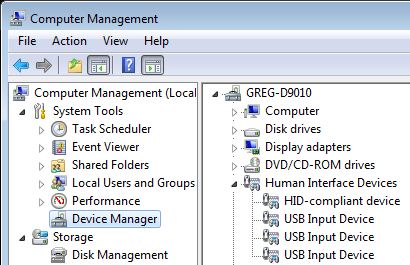
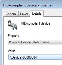
A: This can be caused by a "USB Virtual Device". If you are
not using a virtual machine, please check the USB devices in Control
Panel --> Device Manager for one called "USB Virtual Device". If
this entry exists, please uninstall it.
Do-more
FAQ0035 (similar to DirectSOFT FAQ0066; ECOM FAQ0016; DS Data
FAQ0089)
05-Nov-2019
Q: How can I make a link with Do-more Designer
to single or multiple Do-more CPUs (with on board Ethernet
ports) over the Internet?
A: There are a number of ways to accomplish this due to the
versatile ways in which Internet connectivity is established.
Method #1 (Direct Connect): Requires the remote Do-more CPU(s) to have a registered Internet IP address.
Method #2 (Indirect Connect): Requires access to the remote gateway/router which must be configured to translate TCP port #s.
Method #3 (ISP VPN): Requires the ISP (Internet Service Provider) set up a VPN (Virtual l l Private Network).
Method #4 (VPN Software): Requires the use of some form of VPN software (e.g. PC Anywhere, LogMeIn, etc.).
Multiple Do-more CPU Instructions: In this method it is assumed that each Do-more CPU has its own registered Internet IP address and therefore to connect to each of them only requires that you make separate links to each one.
Do-more Designer Link Configuration to connect to PLC1:
1. Build link in Do-more Designer.
a. On PLC tab select:
PLC Family - Do-more H2 Series
PLC Type - H2-DM1E
b. On the Port tab select:
Devices - Ethernet
Transport Protocol - UDP/IP
Node Address - IP Address xxx.xxx.xxx.xxx (Registered Internet IP Address of your Do-more CPU)
Advanced Settings - Timeout (Increase?)
NOTE: To determine how much the "Timeout" setting should be increased:
1. Go to the DOS Command Prompt (Start --> Programs --> Accessories --> Command Prompt)
2. Type in: ping xxx.xxx.xxx.xxx (Registered Internet IP Address of your Do-more CPU)
3. Make note of the "Maximum" time as listed and increase this number by at least 50%.
4. Enter this number as the "Timeout" setting.
UDP Port Number (if it is displayed) - 28,784 (this is the default; must always be this number*)
*NOTE: The exception to this is if in Do-more Designer System Configuration --> CPU Configuration in the Secondary Ethernet Connection box (available as of Do-more Designer v1.1) the "Enable Secondary Ethernet Connection" is checked and a second UDP Port Number is provided. In this case the Do-more CPU is listening on two UDP ports; the default one (28,784 decimal (7070 hex)) and this secondary UDP Port Number. Thus either one of them can be used in the Do-more Designer Link's UDP Port Number parameter.c. On the Protocol tab select:
Protocols - Do-more
d. Click <Auto>. Should beep for success.
e. Enter a name for the link and click <Accept>.
Multiple Do-more CPU Instructions: In this method if connecting to multiple Do-more CPUs, they are assumed to be located behind the gateway/router on an internal network with internal IP addresses assigned to them. Therefore, the Do-more Designer links to each of them must use the same IP address of the gateway/router (because from the Internet, that is all it can see). Thus, the only way to differentiate between the multiple Do-more CPUs on the other side of the gateway is by Do-more Designer using different TCP port #s for each. In order to accomplish this the remote gateway/router must be configured to translate the TCP port #s to different IP addresses behind its firewall.
Do-more Designer Link Configuration to connect to PLC4:
1. Build link in Do-more Desginer.
a. On PLC tab select:
PLC Family - Do-more H2 Series
PLC Type - H2-DM1E
b. On the Port tab select:
Devices - Ethernet
Transport Protocol - UDP/IP
Node Address - IP Address xxx.xxx.xxx.xxx (Registered Internet IP Address of your Gateway/Router)
Advanced Settings - Timeout (Increase?)
NOTE: To determine how much the "Timeout" setting should be increased:
1. Go to the DOS Command Prompt (Start --> Programs --> Accessories --> Command Prompt
2. Type in: ping xxx.xxx.xxx.xxx (Registered Internet IP Address of your Gateway/Router)
3. Make note of the "Maximum" time as listed and increase this number by at least 50%.
4. Enter this number as the "Timeout" setting.
UDP Port Number - 28,787 (can be any free configurable Port # on your particular Gateway/Router)
c. On the Protocol tab select:
Protocols - Do-more
d. Click <Auto>. Should beep for success.
e. Enter a name for the link and click <Accept>.Gateway Configuration Table:
PLC Do-more Designer Link Node Address (Gateway) Do-more Designer Link Port # Nontranslated Do-more CPU Node Address Do-more CPU Port # (cannot be changed)* PLC1 xxx.xxx.xxx.xxx
(your Gateway/Router IP)28,784 (0x7070) 192.168.20.1 28,784 (0x7070)* PLC2 xxx.xxx.xxx.xxx
(your Gateway/Router IP)
28,785 (0x7071) 192.168.20.2 28,784 (0x7070)* PLC3 xxx.xxx.xxx.xxx
(your Gateway/Router IP)
28,786 (0x7072) 192.168.20.3 28,784 (0x7070)* PLC4 xxx.xxx.xxx.xxx
(your Gateway/Router IP)28,787 (0x7073) 192.168.20.4 28,784 (0x7070)*
*NOTE: The exception to this is if in Do-more Designer System Configuration --> CPU Configuration in the Secondary Ethernet Connection box (available as of Do-more Designer v1.1) the "Enable Secondary Ethernet Connection" is checked and a second UDP Port Number is provided. In this case the Do-more CPU is listening on two UDP ports; the default one (28,784 decimal (7070 hex)) and this secondary UDP Port Number. Thus either one of them can be used in the Do-more Designer Link's UDP Port Number parameter.
This method requires that you work with your ISP (Internet Service Provider) and have them set up a VPN (Virtual Private Network) for you so you can connect to the remote network where the Do-more CPUs are located. There are quite a variety of ways in which your ISP can do this for you. Some may require you use their own software to do it. But in most cases once the VPN is established, the connection to the Do-more CPUs on the remote network is exactly like Method #1 (Direct Connect) above.
Multiple Do-more CPU Instructions: Once VPN connection is established it is assumed that each Do-more CPU has its own IP address on the remote network and therefore to connect to each of them only requires that you make separate links to each one.
This method requires the use of some form of VPN software (e.g. PC Anywhere, LogMeIn, etc.). The Do-more CPU cannot be accessed directly with this method but instead the VPN software allows you to control a PC (with Do-more Designer installed) at the remote site that is on the same network as the Do-more CPUs. Thus, after the connection using the VPN software is established, the connection to the Do-more CPUs on the remote network is exactly like Method #1 (Direct Connect) above.
Multiple Do-more CPU Instructions: Once VPN connection is established it is assumed that each Do-more CPU has its own IP address on the remote network and therefore to connect to each of them only requires that you make separate links to each one.
Do-more
FAQ0036
<REMOVED>
| HARDWARE(1) |
P/N | Upgrade Tool | |||||
| CTRIO Workbench |
ERM Workbench |
WinPLC Workbench |
EZ-Touch |
NetEdit3 |
Do-more Designer |
|
|
| CTRIO/CTRIO2 | H0-CTRIO/2 |
X |
|||||
| H2-CTRIO/2 |
X |
X |
|||||
| H4-CTRIO |
X |
||||||
| T1H-CTRIO/2 |
X |
X | |||||
| DM1/DM1E | H2-DM1/E |
X |
|||||
| T1H-DM1/E |
X |
||||||
| BX-DM1/E |
X |
||||||
| DMIO |
BX-DMIO |
X |
|||||
| EBC/EBC100 | H2-EBC/100 | X |
|||||
| H4-EBC |
X |
||||||
| T1H-EBC/100 |
X |
||||||
| BX-EBC100 |
X |
||||||
| ECOM/ECOM100 | H*-ECOM/100 |
|
X | ||||
| ECOMEX
(POM) |
BX-P-ECOMEX |
X | |||||
| ECOMLT
(POM) |
BX-P-ECOMLT |
X | |||||
| EDRV/EDRV100 | GS-EDRV/100 |
X | |||||
| ERM/ERM100 | H2-ERM/100 |
X | |||||
| H4-ERM/100 |
X | ||||||
| EZ-Ethernet | EZ-Ethernet |
X | |||||
| EZ-EtherPLUS |
X | ||||||
| HSIO | BX-HSIO1/2/4 |
X | |||||
| MBIO |
BX-MBIO |
X | |||||
| MB-GATEWAY |
MB-GATEWAY |
X | |||||
| Profibus | H0-PSCM |
X | |||||
| H2-PBC |
X | ||||||
| T1H-PBC |
X | ||||||
| SERIO/SERIO4(2) | H2-SERIO/4 |
||||||
| BX-SERIO/4 |
|||||||
| WinPLC |
H2-WPLCx |
X | |||||
NOTES:
(1) All
the firmware, except for the DM1/DM1E, can be downloaded using
NetEdit3's File --> Live Update. The firmware files are
stored in c:\Users\Public\Documents\HAPTools\Images folder. For the
DM1/DM1E and CTRIOs used with DM1/DM1E, the firmware is under
c:\Users\Public\Documents\Do-more\Designer2_8\Bin\Images and you can
download the latest for those devices in Do-more Designer using PLC
--> Update Firmware or PLC --> Monitor CTRIO Module.
(2) These are not
field-upgradable but very rarely ever need upgrading.
Do-more
FAQ0039
17-Jul-2024
Q: What instruction is best for moving/copying data?
A: Choose the type of operation you want in the leftmost column
and then move along that row to see what Do-more instruction can do
that operation best for you. See also Do-more Designer Help Topic
DMD0431.
| OPERATION | INSTRUCTION
as of v2.10.1 |
|||||||||||||||||||||
| COPY |
INIT |
MAPIO |
MEMCLEAR
(7) |
MEMCOPY |
MOVE |
MOVEBIT |
MOVER |
PUBLISH
(8) |
REFWRITE
(7) |
SETNUMR |
SUBSCRIB
(8) |
STRPRINT
(7) |
STRSUB
(7) |
STRCLEAR |
STRCOPY | STRCOPYR | RST |
RSTR |
SET |
SETR |
OUT |
|
| Bit OFF | Y |
Y | Y | Y | Y | Y | Y | Y | ||||||||||||||
| Bit
ON |
Y |
Y | Y | Y | Y | Y | Y | |||||||||||||||
| Bit
range
OFF |
Y |
Y | Y | Y(6) |
Y(6) |
Y(6) |
Y | |||||||||||||||
| Bit
range
ON |
Y |
Y | Y(6) |
Y(6) |
Y(6) |
Y | ||||||||||||||||
| Bit
to
bit |
Y |
Y | Y | Y | Y | Y | Y | Y | Y | |||||||||||||
| Bit
to
bit range |
Y(1) |
Y(1) |
Y(1) |
|||||||||||||||||||
| Bit
range
to bit range |
Y |
Y(2) |
Y(2) |
Y | Y(6) |
Y | Y(6) |
Y(6) |
Y(6) |
|||||||||||||
| Value
to
memory |
Y |
Y | Y(3) |
Y | Y | Y | Y | Y | ||||||||||||||
| Value
to
memory range |
Y |
Y | Y(3) |
Y | Y | Y | ||||||||||||||||
| Memory
to
memory |
Y |
Y | Y | Y | Y | Y | Y | Y | Y | Y | ||||||||||||
| Memory
to
memory range |
Y(1) |
Y | Y(1) |
Y | ||||||||||||||||||
| Memory
range
to memory range |
Y |
Y(2) |
Y(2) |
Y | Y(6) |
Y | Y | Y | ||||||||||||||
| Text
to
string |
Y |
Y(4) |
Y | Y(4) |
Y | |||||||||||||||||
| Text
to
string range |
Y |
Y(4) |
Y(4) |
Y | ||||||||||||||||||
| String
to
string |
Y |
Y | Y | Y | Y | Y | ||||||||||||||||
| String
to
string range |
Y(1) |
Y | ||||||||||||||||||||
| String
range
to string range |
Y |
Y | Y | |||||||||||||||||||
| Value
to
structure |
Y |
Y(5) |
||||||||||||||||||||
| Structure
to
structure |
Y |
Y | ||||||||||||||||||||
| Structure
to
structure range |
Y(1) |
|||||||||||||||||||||
| Structure
range
to structure range |
Y |
Y | |
|||||||||||||||||||
| Structure
to
memory range |
Y | |||||||||||||||||||||
| Structure
range
to memory range |
Y | |||||||||||||||||||||
| Memory
range
to structure |
Y | |||||||||||||||||||||
| Memory
range
to structure range |
Y | |||||||||||||||||||||
NOTES:
(1)
Using multiple table entries of same locaton to multiple locations
(2) Using multiple
table entires for individual locations
(3) Can only write a
zero
(4) Can only clear
the string
(5) Can only clear
all the structure members (zeros; OFF)
(6) Only possible
with casting
(7) Does not support
casting
(8) Supports
unaligned memory (e.g. V1/V2 as a double-word instead of requiring V0/V1
as a double-word)
The following files and file extensions are used with some of the built-in utilities:
The following files are created by Do-more Designer for its own use:
")


The easiest fix is to write "1" to DST24 and DST25 on the first scan of the PLC. Use $tFirstScan System Task code block; like this:


PART #
|
Do-more
Designer
Version |
DESCRIPTION |
||||||||
| v2.0 |
v2.1 |
v2.3 |
v.2.5 |
v2.6 | v2.7 | v2.8 |
v2.9 | v2.10 |
||
| DC Input Modules |
||||||||||
| BX-08ND3 |
X |
8in,
12-24VDC, sink/source |
||||||||
| BX-12ND3 |
X |
12in,
12-24VDC, sink/source |
||||||||
| BX-16ND3 |
X |
16in,
12-24VDC, sink/source |
||||||||
| BX-32ND3 |
X |
32in,
12-24VDC, sink/source |
||||||||
| BX-08NF3 |
X |
8in, 3-5VDC,
sink/source |
||||||||
| BX-16NF3 |
X | 16in,
3-5VDC, sink/source |
||||||||
| BX-08SIM |
X | 8in, SPST
dipswitches |
||||||||
| DC Output Modules | ||||||||||
| BX-08TD1 |
X | 8out,
12-24VDC, sink |
||||||||
| BX-08TD2 |
X | 8out,
12-24VDC, source |
||||||||
| BX-12TD1 |
X | 12out,
12-24VDC, sink |
||||||||
| BX-12TD2 |
X | 12out,
12-24VDC, source |
||||||||
| BX-16TD1 |
X | 16out,
12-24VDC, sink |
||||||||
| BX-16TD2 |
X | 16out,
12-24VDC, source |
||||||||
| BX-32TD1 |
X | 32out,
12-24VDC, sink |
||||||||
| BX-32TD2 |
X | 32out,
12-24VDC, source |
||||||||
| BX-16TF2 |
X | 16out, 5VDC
TTL, source |
||||||||
| DC Combo Modules |
||||||||||
| BX-08CD3R |
X | 4in,
12-24VDC, sink/source 4out relay, 12-24VDC/12-240vac, SPST |
||||||||
| BX-12CD3D1 |
X | 8in,
12-24VDC, sink/source 4out, 12-24VDC, sink |
||||||||
| BX-12CD3D2 |
X | 8in,
12-24VDC, sink/source 4out, 12-24VDC, source |
||||||||
| BX-16CD3D1 |
X | 8in,
12-24VDC, sink/source 8out, 12-24VDC, sink |
||||||||
| BX-16CD3D2 |
X | 8in,
12-24VDC, sink/source 8out, 12-24VDC, source |
||||||||
| BX-16CF3F2 |
X | 8in, 5VDC
TTL, sink/source 8out, 5VDC TTL, source |
||||||||
| AC Input Modules |
||||||||||
| BX-08NB |
X |
8in,
12-24vac |
||||||||
| BX-12NB |
X | 12in,
12-24vac |
||||||||
| BX-16NB |
X | 16in,
12-24vac |
||||||||
| BX-08NA |
X | 8in,
120-240vac |
||||||||
| BX-12NA |
X | 12in,
120-240vac |
||||||||
| BX-16NA |
X | 16in,
120-240vac |
||||||||
| AC Output Modules | ||||||||||
| BX-08TA |
X | 8out,
120-240vac |
||||||||
| BX-12TA |
X | 16out,
120-240vac |
||||||||
| Relay Output Modules |
||||||||||
| BX-08TR | X | 8out relay, 12-48VDC/12-240vac, SPST | ||||||||
| BX-12TR |
X |
12out relay,
12-48VDC/12-240vac, SPST |
||||||||
| BX-16TR |
X |
16out relay,
12-48VDC/12-240vac, SPST |
||||||||
| BX-05TRS |
X |
5out relay,
12-48VDC/12-240vac, SPDT |
||||||||
| BX-05TRS-1 | X | 5out relay, 12-48VDC/12-240vac / 100-125VDC, high current, SPST |
||||||||
| BX-08TRZ | X | 8out relay, dry contact |
||||||||
| BX-16TRZ | X | 16out relay, dry contact |
||||||||
| Analog Input Modules |
||||||||||
| BX-04ADM-1 |
X |
4in,
0/4-20mA, sink, 14-bit |
||||||||
| BX-04AD-1 |
X | 4in,
0/4-20mA, sink, 16-bit |
||||||||
| BX-08AD-1 |
X | 8in,
0/4-20mA, sink, 16-bit |
||||||||
| BX-16AD-1 |
X | 16in,
0/4-20mA, sink, 16-bit |
||||||||
| BX-04AD-2B |
X | 4in,
+/-10VDC, sink, 16-bit |
||||||||
| BX-08AD-2B |
X | 8in,
+/-10VDC, sink, 16-bit |
||||||||
| BX-16AD-2B |
X | 16in,
+/-10VDC, sink, 16-bit |
||||||||
| BX-04AD-3 |
X | 4in,
universal: +/-10VDC, +/-20mA |
||||||||
| BX-08AD-3 |
X | 8in,
universal: +/-10VDC, +/-20mA |
||||||||
| Analog Output Modules | ||||||||||
| BX-04DA-1 |
X | 4out,
0/4-20mA, source, 16-bit |
||||||||
| BX-08DA-1 |
X | 8out,
0/4-20mA, source, 16-bit |
||||||||
| BX-04DA-2B |
X | 4out,
+/-10VDC, source, 16-bit |
||||||||
| BX-08DA-2B |
X | 8out,
+/-10VDC, source, 16-bit |
||||||||
| BX-04DA-3 |
X | 4out,
universal: +/-10VDC, +/-20mA |
||||||||
| BX-08DA-3 |
X | 8out,
universal: +/-10VDC, +/-20mA |
||||||||
| Analog Combo Modules |
||||||||||
| BX-2AD2DA-1 |
X | 2in,
0/4-20mA, sink, 16-bit 2out, 0/4-20mA, source, 16-bit |
||||||||
| BX-4AD2DA-1 |
X | 4in,
0/4-20mA, sink, 16-bit 2out, 0/4-20mA, source, 16-bit |
||||||||
| BX-2AD2DA-2B |
X | 2in,
+/-10VDC, sink, 16-bit 2out, +/-10VDC, source, 16-bit |
||||||||
| BX-4AD2DA-2B |
X | 4in,
+/-10VDC, sink, 16-bit 2out, +/-10VDC, source, 16-bit |
||||||||
| BX-2AD2DA-3 |
X | 2in,
+/-10VDC, +/-20mA 2out, +/-10VDC, +/-20mA |
||||||||
| BX-4AD4DA-3 |
X | 4in,
+/-10VDC, +/-20mA 4out, +/-10VDC, +/-20mA |
||||||||
| BX-4THM4DA-1 |
X | 4in,
thermocouple, 16-bit 4out, +/-10VDC, source, 16-bit |
||||||||
| BX-4RTD4DA-1 |
X | 4in, RTD,
16-bit 4out, +/-10VDC, source, 16-bit |
||||||||
| BX-4UT4DA-3 |
X | 4in,
universal: thermocouple/RTD/thermistor 4out, +/-10VDC, +/-20mA |
||||||||
| BX-4UT4TD1 |
X | 4in,
universal: thermocouple/RTD/thermistor 4out, 24VDC, sink |
||||||||
| BX-4UT4TD2 |
X | 4in,
universal: thermocouple/RTD/thermistor 4out, 24VDC, source |
||||||||
| BX-4UT4TR |
X | 4in,
universal: thermocouple/RTD/thermistor 4out, Form A relay |
||||||||
| Temperature Input Modules |
||||||||||
| BX-04THM |
X | 4in,
thermocouple, 16-bit |
||||||||
| BX-08THM |
X | 8in,
thermocouple, 16-bit |
||||||||
| BX-06RTD |
X | 6in, RTD,
16-bit |
||||||||
| BX-08NTC |
X | 8in,
thermistor, 16-bit |
||||||||
| BX-04UT |
X | 4in,
universal: thermocouple/RTD/thermistor |
||||||||
| BX-08UT |
X | 8in,
universal: thermocouple/RTD/thermistor |
||||||||
| Specialty |
||||||||||
| BX-HSIO1 |
X |
8ch,
high-speed in, 12-24VDC, sink/source 8ch, high-speed out, 12-24VDC, sink |
||||||||
| BX-HSIO2 |
X | 8ch,
high-speed in, 12-24VDC, sink/source 8ch, high-speed out, 12-24VDC, source |
||||||||
| BX-HSIO4 |
X | 8ch,
high-speed in, 2MHz, 5VDC, sink/source 8ch, high-speed out, 2MHz, 5VDC, source |
||||||||
| BX-SERIO |
X | 4port,
serial comm, RS-232/RS-485 |
||||||||
| BX-SERIO-2 |
X | 4port,
serial comm, RS-232 flow control |
||||||||
| BX-SERIO-4 |
X | 4port,
serial comm, RS-422 |
||||||||
| BX-APAD |
X | Active pad,
emulates other BRX I/O |
||||||||
| Expansion Analog I/O Functionality? |
||||||||||||||
Booter |
OS |
|||||||||||||
| 2.1.0 |
2.2.0 |
2.2.1 |
2.3.0 |
2.3.1 |
2.3.2 |
2.4.0 |
2.5.0 |
2.5.1 |
2.5.2 |
2.6.0 |
2.6.1 |
2.6.2 |
2.6.3 |
|
| 1.0.0 |
Yes |
Yes | Yes | Yes | Yes | Yes | Yes | Yes | Yes | Yes | Yes | Yes | Yes | Yes |
| 1.0.2 |
Yes |
Yes | Yes | Yes | Yes | Yes | Yes | Yes | Yes | Yes | Yes | Yes | Yes | Yes |
| 1.0.3 |
Yes |
Yes | Yes | Yes | Yes | Yes | Yes | Yes | Yes | Yes | Yes | Yes | Yes | Yes |
| 1.0.5 |
No |
No | No | No | No | No | Yes | Yes | Yes | Yes | Yes | Yes | Yes | Yes |
| 1.0.6 |
No |
No | No | No | No | No | Yes | Yes | Yes | Yes | Yes | Yes | Yes | Yes |
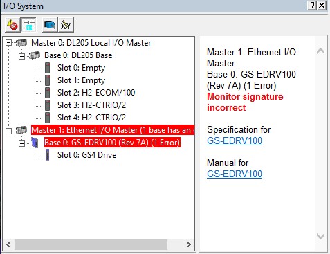
Solution: Make
sure there is only one Ethernet I/O master, then power-cycle the
slave. In future releases, the wording of this error may make the
issue more readily apparent to the user.
Explanation: The "Monitor signature" actually
monitors the link between master and slave. It contains a GUID
(Globally Unique Identifier) that is utilized in the master's and
slave's telegrams to each other. This helps ensures that only one
master can control a particular slave.

But by use of these Block Transfer
Parameters, all 3 of these could be written to with one telegram.

In the GS-Drives, the mapping of these parameters is generally the same for the GS1, GS2, and GS3 drives, but quite a bit different in the GS4. The mapping looks like this:
| Drive Parameter | GS1(1) | GS2(1) | GS3(1) | GS4(2) |
| P9.09 | Block
Transfer Parm 1 |
|||
| P9.10 | Block
Transfer Parm 2 |
|||
| P9.11 |
Block Transfer Parm 1 |
Block
Transfer Parm 3 |
||
| P9.12 |
Block Transfer Parm 2 |
Block
Transfer Parm 4 |
||
| P9.13 |
Block Transfer Parm 3 | Block
Transfer Parm 5 |
||
| P9.14 |
Block Transfer Parm 4 |
Block
Transfer Parm 6 |
||
| P9.15 |
Block Transfer Parm 5 |
Block
Transfer Parm 7 |
||
| P9.16 |
Block Transfer Parm 6 |
Block
Transfer Parm 8 |
||
| P9.17 |
Block Transfer Parm 7 |
Block
Transfer Parm 9 |
||
| P9.18 |
Block Transfer Parm 8 |
Block
Transfer Parm 10 |
||
| P9.19 |
Block Transfer Parm 9 |
Block
Transfer Parm 11 |
||
| P9.20 |
Block Transfer Parm 10 |
Block
Transfer Parm 12 |
||
| P9.21 |
Block Transfer Parm 11 |
Block
Transfer Parm 13 |
||
| P9.22 |
Block Transfer Parm 12 |
Block
Transfer Parm 14 |
||
| P9.23 |
Block Transfer Parm 13 |
Block
Transfer Parm 15 |
||
| P9.24 |
Block Transfer Parm 14 |
Block
Transfer Parm 16 |
||
| P9.25 |
Block Transfer Parm 15 |
|||
NOTES:
(1) To set the pointers for these
locations, it must be done manually from the GS drive's keypad.
(2) To set the pointers for
these locations, it can be done manually, or by writing the pointer to
P9.69 through P9.84 respectively
Notice how the GS4 shifted these up
two locations, and also has one more parameter to work with (16
instead of just 15 like the GS1, GS2, and GS3.)
When used with the GS-EDRV100 in a Do-more PLC these Block Transfer
Parameters are mapped into the Do-more PLC's GS-EDRV100 device memory
structure when you configure the GS-EDRV100 as a Do-more Ethernet I/O
slave.
How to normally use with GS1, GS2, and GS3 without
Do-more:
How to use with GS4 without Do-more:
How
Do-more uses GS-Drives: Unless you are going to
manage the Modbus communications manually to the drives, then an
easier way to use the GS-Drives with a Do-more PLC is to use a
GS-EDRV100 for each drive. Then in the Do-more PLC utilize the
Ethernet I/O built-in port and enslave each GS-EDRV100.
In this manner, automatic communications are established, and
the more-commonly-used drive parameters are automatically
mapped to the structure memory of the Do-more PLC for easy
read/write (output frequency, status monitor 1 & 2, run command,
etc). Also, nearly any drive parameter can be read from or written to
using the GSREGWR and GSREGRD instruction. Here is a
list of the GS-EDRV100 Do-more structure memory members and their
corresponding GS-Drive parameters:
| Structure Member | Size(*) | GS1 | GS2 | GS3 | GS4 |
| .OutputFrequency | Word/RO | / 48452 |
|||
| .OutputCurrent | Word/RO | / 48453 |
|||
| .StatusMonitor1 | Word/RO | P6.31 / 48449 |
|||
| .StatusMonitor2 | Word/RO | / 48450 |
|||
| .RunCommand | Word/RW | P9.27 / 42332 |
|||
| .RS485SpeedRef | Word/RW | P9.26 / 42331 |
|||
| .ExtCommFault | Bit/RO | P9.29 / 42334 |
|||
| .IntCommFault | Bit/RO | <GS-EDRV100> |
|||
| .Direction | Bit/RW | P9.28 / 42333 |
|||
| .ResetCommFault | Bit/RW | P9.30 / 42335 |
|||
| .BlockParm1 | Word/RW | P9.11 / 42316 |
P9.09 / 42314 | ||
| .BlockParm2 | Word/RW | P9.12 / 42317 |
P9.10 / 42315 | ||
| .BlockParm3 | Word/RW | P9.13 / 42318 |
P9.11 / 42316 | ||
| .BlockParm4 | Word/RW | P9.14 / 42319 |
P9.12 / 42317 | ||
| .BlockParm5 | Word/RW | P9.15 / 42320 |
P9.13 / 42318 | ||
| .BlockParm6 | Word/RO | P9.16 / 42321 |
P9.14 / 42319 | ||
| .BlockParm7 | Word/RO | P9.17 / 42322 |
P9.15 / 42320 | ||
| .BlockParm8 | Word/RO | P9.18 / 42323 |
P9.16 / 42321 | ||
| .BlockParm9 | Word/RO | P9.19 / 42324 |
P9.17 / 42322 | ||
| .BlockParm10 | Word/RO | P9.20 / 42325 |
P9.18 / 42323 | ||
| .BlockParm11 | Word/RO | P9.21 / 42326 |
P9.19 / 42324 | ||
| .BlockParm12 | Word/RO | P9.22 / 42327 |
P9.20 / 42325 | ||
| .BlockParm13 | Word/RO | P9.23 / 42328 |
P9.21 / 42326 | ||
| .BlockParm14 | Word/RO | P9.24 / 42329 |
P9.22 / 42327 | ||
| .BlockParm15 | Word/RO | P9.25 / 42330 |
P9.23 / 42328 | ||
| Word | P9.24 / 42329 | ||||
(*)
RO = Read Only, RW = Read/Write
Because the Structure
Members are updated constantly with the regular I/O cycle, we chose to
only make Block Parameters 1-5 as writable (pink background in above
chart). The other ones (6-15) are read-only (light blue background in
above chart). Thus to read and write these parameters only requires
using them in Ladder logic (or Data View) as you would any other
memory Element in the Do-more PLC.
- Current
Size: This shows the total amount of Image Register memory
currently used by the System Memory Blocks, User Memory Blocks, and
Heap Items. It is calculated by adding up the size of each Memory
Block and Heap Item and subtracting it from the Max Size.
The only extra thing here is there will be an extra 4160 bytes
included in this number in which the details are not shown in this
display. These extra bytes are used by the PLC's system for various
necessary overhead.
- Max Size: This shows the maximum size possible for
the Image Register.
- Space Available: This shows the available Image
Register space. It is the difference between Max Size
and Current Size.
Thus, if you click on each
individual entry in the Memory Blocks table, and each individual entry
in the Heap Items table, and look down at the bottom of the table, you
can see the size of that individual entry shown in bytes (as shown in
the pic below). If you painstakingly do this and record each block's
size, add them up, and then add the 4160 bytes of hidden system
memory, you will come to the value shown in the Current Size
parameter.


| BRX CPU | Do-more Designer | |||||||
| v2.8
or earlier |
v2.9 or later |
|||||||
| Firmware | Booter | Firmware | Booter | |||||
| Upgrade | Downgrade | Upgrade | Downgrade | Upgrade | Downgrade | Upgrade | Downgrade | |
| Hardware: 5x |
Yes | Yes | Yes | Yes | Yes | Yes | Yes | Yes |
| Hardware: 6x | Yes | Yes | Yes | Yes | Yes | Yes | Yes | Yes |
| Hardware: 8x | Yes | Yes | Yes | Yes | Yes | Yes | Yes | Yes |
| Hardware: 2x Firmware: 2.9.1 Booter: 1.1.0 |
Yes | No (1) | No (2) | No (1) | Yes | No (1) | Yes | No (3) |


| SOFTWARE WATCHDOG (DEFAULT BEHAVIOR) |
---> DEFAULT BEHAVIOR ---> | |||||
| STARTING CONDITION |
W A T C H D O G |
PLC transitions from RUN --> STOP (4) |
S W I T C H T O R U N |
PLC transitions from STOP --> RUN (5) |
||
| CONFIG | ST37 $DisableSwWdog |
OFF | - | - | ||
| DST23 $WatchdogTimeVal |
1000 | - | - | |||
| PARMS | ST15 $PgmModeRestart |
OFF | - | ON | ||
| ST128 $WatchdogTimeout |
OFF | ON | OFF | |||
| DST5 $Errors |
0 | 1 (1) | 0 | |||
| DST30 $LastError1 |
0 | 33 (2) | 0 | |||
| DST51 $FatalTermCode |
0 | 1 (3) | 0 | |||
NOTES:
- The '-' means no change in the status
(1) A value of 1 means Bit0 of this
status word is ON, indicating WATCHDOGTIMEOUT
(2) A value of 33 means WATCHDOGTIMEOUT
- Watchdog timeout.
(3) A value of 1 has numerous meanings,
one of which is, "...watchdog timeout..." This value will be a
5 if induced by the WATCHDOG
instruction.
(4) A date/time stamped entry is made
in the System Event Log (PLC --> System Information... -->
Event Log): "Program was halted due to the software
watchdog firing."
(5) A date/time stamped entry is made
in the System Event Log (PLC --> System Information... -->
Event Log): "Default User changed mode to RUN"
| SOFTWARE WATCHDOG (DISABLED) |
---> DISABLED ---> | |||
| STARTING CONDITION |
W A T C H D O G |
PLC stays in RUN |
||
| CONFIG | ST37 $DisableSwWdog |
ON | - | |
| DST23 $WatchdogTimeVal |
1000 | - | ||
| PARMS | ST15 $PgmModeRestart |
OFF | - | |
| ST128 $WatchdogTimeout |
OFF | - | ||
| DST5 $Errors |
0 | - | ||
| DST30 $LastError1 |
0 | - | ||
| DST51 $FatalTermCode |
0 | - | ||
| HARDWARE WATCHDOG (DEFAULT BEHAVIOR) |
---> DEFAULT BEHAVIOR ---> | ||||||
| STARTING CONDITION |
W A T C H D O G |
PLC reboots & returns to RUN (2) |
After 10th reboot, PLC remains in STOP (2) |
S W I T C H T O R U N |
PLC transitions from STOP --> RUN (3) |
||
| IG | ST24 $HwWatchdogMode |
OFF | - | - | - | ||
| ST25 $DisableHwWdog |
OFF | - | - | - | |||
| PARMS | ST13 $WatchdogReboot |
OFF | - | ON | OFF | ||
| ST15 $PgmModeRestart |
OFF | - | - | ON | |||
| DST385 $WatchdogReboots |
0 | 1...9 (1) | 0 | 0 | |||
| HARDWARE WATCHDOG (SHUTDOWN MODE) |
---> SHUTDOWN MODE ---> | |||||
| STARTING CONDITION |
W A T C H D O G |
PLC shutsdown, all lights RED |
P O W E R C Y C L E |
PLC returns to RUN (1) |
||
| CONFIG | ST24 $HwWatchdogMode |
ON | (?) | OFF |
||
| ST25 $DisableHwWdog |
OFF | (?) | - | |||
| PARMS | ST13 $WatchdogReboot |
OFF | (?) | - | ||
| ST15 $PgmModeRestart |
OFF | (?) | - | |||
| DST385 $WatchdogReboots |
0 | (?) | - | |||
| HARDWARE WATCHDOG (DISABLED) |
---> DISABLED (1) ---> | |||||
| STARTING CONDITION |
W A T C H D O G |
PLC locks up, lights freeze, no comms |
P O W E R C Y C L E |
PLC returns to RUN (3) |
||
| CONFIG | ST24 $HwWatchdogMode |
X (2) |
(?) | OFF |
||
| ST25 $DisableHwWdog |
ON | (?) | OFF | |||
| PARMS | ST13 $WatchdogReboot |
OFF | (?) | - | ||
| ST15 $PgmModeRestart |
OFF | (?) | - | |||
| DST385 $WatchdogReboots |
0 | (?) | - | |||