Topic: DMD0194

DMLoader - Do-more Loader
The DMLoader utility will use an image file built by Generate Do-more Loader Image to update a Do-more CPU with the contents of that image file. DMLoader can use USB, Serial, or Ethernet connection to the destination Do-more CPU to perform the update.
When DMLoader opens, you will be prompted for the DMLoader image file to open. If the image file was created with a password you will be prompted to enter that password before the file can be opened.
After an image file is selected and successfully opened the main DMLoader dialog will be displayed. The image below has the default Do-more Loader banner at the top and the default instructions in the bottom section. If the image was created with custom banner and / or instructions these would be displayed instead.
Click the Load Image button to open a different DMLoader image file.
Click the Open Instructions in external app... button to open the instructions in the computer's default application for .RTF files - this could be Notepad, Wordpad, Microsoft Word, etc.. This allows you to have the instructions available on-screen when you move to the next section of the DMLoader process.
Once the correct image file is open, and the instructions are where you want them, click the Next button move to the next section.

Establish Communication Link to the Destination CPU
This section of the dialog will establish the required communication link to the destination CPU. You can elect to use the USB or Serial or the Ethernet port (if available) on the destination CPU to establish the communication link. Once the connection port is selected and configured (if necessary) then click the Test Link to Continue ... button to verify that the link is functional before continuing to the next section where the update will be performed. If the link test is successful the information at the bottom of the dialog will be populated to allow confirmation the selected CPU is the correct target CPU.
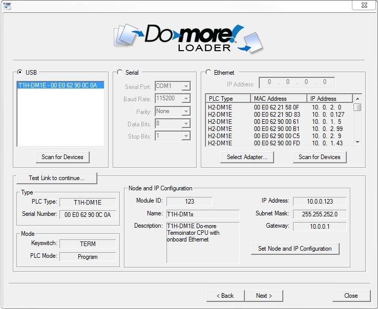
Step 1: Select the communication port to use
Select USB to use the USB port to perform the update operation. If the USB cable was connected when DMLoader was started, the destination CPU's USB address will already be in the list of USB devices found. If multiple Do-more CPUs are displayed highlight the one you want in the list.
Click Scan for Devices to re-scan the USB port to find a newly connected Do-more CPU. Note: if the connected Do-more CPU is NOT in the list of USB devices after a re-scan operation make sure that no other application - like Do-more Designer - is currently using that USB connection to the CPU.
Select Serial to use a serial port on the PC to connect to the CPU:
Serial Port will list the serial ports that are configured on this computer, for example: COM1, COM2, etc.
Baud Rate: 115200, 57600, 38400, 19200, 9600, 4800, 2400, 1200, 300
Data Bits: 5, 6, 7, 8
Select Ethernet to have DMLoader query the network for Do-more CPUs that are currently connected to the same network. If the destination CPU is new (and does not have a TCP/IP configuration) or has an incorrect TCP/IP configuration, this can be addressed in Step 3 that follows.
Select the desired destination CPU from the list and it's currently configured IP address will be displayed in the IP Address field.
If the PC has multiple Ethernet Adapters installed, click Select Adapter to choose which of the PC's Ethernet adapters to use when connecting to the Do-more CPU and perform another scan for Do-more CPUs on the network.
Click Scan for Devices to manually perform the network query to scan for Do-more CPUs.
Step 2: Test the communication link to verify connectivity
After the port has been selected, click the Test Link to Continue... to validate the communication link. If the validation process is successful DMLoader will read a series of data points to verify the connection to the proper CPU.
Note: the default values used in the communication link for Timeout is 250 ms, and for retries is 3. If needed, these two values can be adjusted through the use of a text file to override the default settings. The following steps outline what's need to change these two values:
1. create a text file named DMLoader.Ini in the same folder where DMLoader.exe resides.
2. that file needs to contain only the following three lines of text:
[Settings]
Retries=3
Timeout=250
3. Change the retries and / or timeout values to suit your needs.
4. start DMLoader as normal and the new Retries and Timeout values will be used when making the connection attempt to the CPU.
After successful communication is established with the target CPU, the following fields will display information read from the connected CPU:
Type displays the type of CPU hardware and identification:
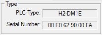
PLC Type displays the type of CPU hardware.
BX-DM1-xxx : BRX Series Do-more CPU
BX-DM1E-xxx : BRX Series Do-more CPU with on-board Ethernet
H2-DM1 : DL205 Series Do-more CPU
H2-DM1E : - DL205 Series Do-more CPU with on-board Ethernet
T1H-DM1 : Terminator I/O Series Do-more CPU
T1H-DM1E : Terminator I/O Series Do-more CPU with on-board Ethernet
Serial Number is the 12 digit serial number of the CPU
Do-more CPUs without on-board Ethernet is a serialized number assigned at the factory
Do-more CPUs with on-board Ethernet is the MAC address of the Ethernet port
DM-SIM is the MAC address of the primary Ethernet adapter in the PC running the Do-more Simulator
Mode displays information about the current PLC mode:
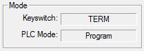
Keyswitch is the current position of the front panel keyswitch:
RUN means the keyswitch is in the RUN position.
PLC Mode displays the current PLC mode:
Run means the CPU is running the project.
Optional Step 3: Setting up the TCP/IP configuration for a Do-more CPU that has an on-board Ethernet port
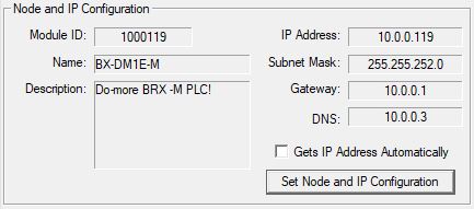
Node and IP Configuration displays the current Node configuration and the setup of the on-board Ethernet port (on models that have them). These values are initially configured by the NetEdit utility. The values of the fields are also stored in the CPU's memory in these locations: $IPAddress (DST18), $NetMask (DST19), $Gateway (DST20).
Click the Set Node and IP Configuration button to open a dialog that will allow you to change these entries.
Note: the ability to change the TCP/IP configuration of a Do-more CPU through its USB or Serial port is a convenient way to set the TCP/IP configuration of a CPU that is not configured to be part of the local network.
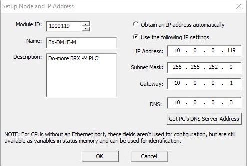
The Module ID can be any positive constant number.
The Name can be any 255 character combination of alphanumeric and punctuation characters. The Module ID and Names entered must be unique on the network where the CPU will be connected.
The Description can be any 255 character combination of alphanumeric and punctuation characters.
The TCP/IP Address information entered in the following three fields must be valid for the network where the CPU will be connected. For Do-more CPUs that do not have an on-board Ethernet port these fields are not used for configuration purposes, but the data in these fields can still be used for identification by storing values in their associated status memory locations: $IPAddress (DST18), $NetMask (DST19), $Gateway (DST20).
The IP Address can be any valid TCP/IP Address The IP Address entered must be unique on the network where the CPU will be connected.
The Subnet Mask can be any valid TCP/IP Subnet Mask for the network.
The Gateway can be any valid TCP/IP address of a network Gateway.
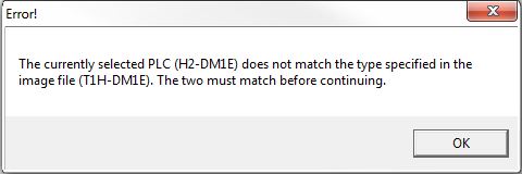
After the communication link is established click the Next button to move to the final section where the update is performed. At this point a final check is made of the communication link to make sure that the on-screen selections still are still valid for the Do-more CPU that is physically connected.
If at this point the connected CPU does not match the on-screen selections an error message similar to the following is displayed:
.
Perform the Update
The final step is the actual downloading of the image contents to the destination CPU. The left-side control will display a list of the operations that will be performed based on the contents of the image file that was opened. The right-hand control will display the log entries generated by each step of the update process.
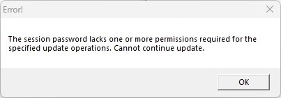
Click the Start Update button will begin the update process by opening a comm session to the selected CPU. If a Comm Session Password was specified when the DMLoader Image was created, that password will be used to establish the connection to the CPU. If the CPU does not already have that password in its Password Configuration, or if the CPU's configuration for that password does not have sufficient privileges to restore the components included in the DMLoader Image, an error similar to the following is displayed:
Once the session is established the downloading of the image contents will begin. The current step in the process and a progress indicator for that step are displayed to the right of the button.
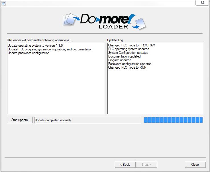
Once the update process concludes, you can use the Back button to return to the previous step and select a different Do-more CPU to update, or click Close to exit DMLoader.
Related Topics: