Topic: DMD0286

Print / Print Preview
Note: it is highly recommended that you use Print Preview to view the potential output BEFORE sending the output to a printer, because the size of the program and the options selected can generate an enormous print output.
The Print and Print Preview facility is a general purpose tool that is used by the Ladder View, Documentation View, and Cross Reference Views to generate a printable version of the their view-specific data.
The Print dialog is used to generate a hard copy of the view-specific data. The Print dialog can be invoked by selecting the File -> Print menu selection, or pressing Ctrl + P.
The Print Preview dialog is used to see how the view-specific data will appear on a printed page and allow an opportunity to make adjustments to improve its appearance before actually sending the data to the printer. The Print Preview dialog is invoked by selecting the File -> Print Preview menu selection.
Note: the Print All dialog can be used to generate a hard copy of the Ladder Views, Documentation Views, and the Cross Reference at one time.
Print and Print Preview for Ladder View
When Print or Print Preview is invoked from a Ladder View, the top section of the dialog contains options used to generate a hard copy of the ladder logic in the single code-block where the Print operation was initiated.
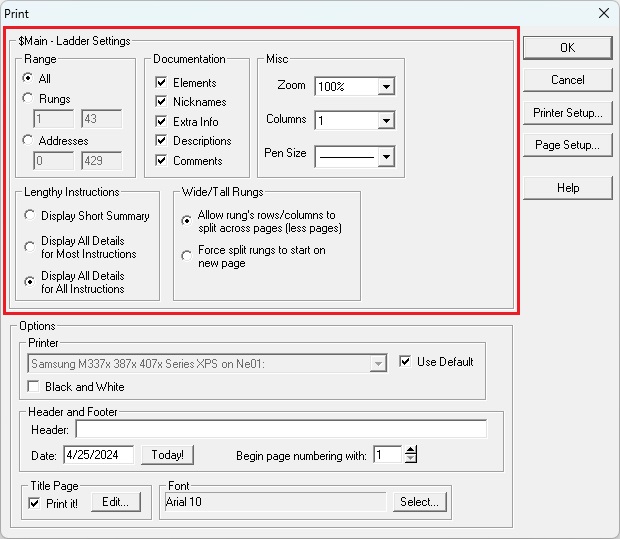
The Range group defines how much of the code-block to print.
-
Select All to print all of the ladder logic in the code-block.
-
Select Rungs to print only the specified range of rungs in the code-block. Enter the first and last rung to print in the fields provided.
-
Select Addresses to print only the specified range of addresses in the code-block. Enter the first and last address to print in the fields provided.
The Documentation group defines which of the project documentation to include on the printout.
Check Elements to include the element name (e.g. X0, R0, etc.).
Check Nicknames to include element nicknames (e.g. MotorStart, Pump27, etc.).
Check Extra Info to include element wiring info (e.g. Blue - 10).
Check Descriptions to include element descriptions (e.g. This is the Motor Starter ).
Check Comments to include all of the rung comments in the code-block.
The Misc group defines the line drawing characteristics
Zoom sets the zoom level that will be used to generate the printout, select from 35%, 55%, 65%, 75%, 85%, 100%, 125%, 150%, 175%, 200%, or 225%.
Columns designates how many columns will be on each page, select from 1, 2, or 3.
Pen Size designates the width of the pen used to draw the rungs and elements, there are 4 sizes to pick from.
The Lengthy Instructionsoptions select how to handle instructions that have a variable number of rows (e.g. INIT- Initialize Data, RAMPSOAK - Ramp / Soak Profile, etc. which could consume a lot of vertical space on a page:
-
Display Short Summary will print the smallest amount of information that is practical, typically this will be the first couple of rows and the last couple rows in the instruction.
-
Display All Details for Most Instructions (default) will print every row for the majority of these instructions because there are only a few that always use a lot of screen real estate and printed pages.
-
Display All Details for All Instructions will always print every row of these instructions, regardless of the amount of screen real estate or number of printed pages that is required.
The Wide / Tall Rungs options select how to handle rungs that consume a lot of horizontal and / or vertical space on a page:
-
Allow rung's rows / columns to split across pages (less pages) will allow rungs that are too wide or too tall to fit on a single page or the remaining space on the current page to be split across pages
-
Selecting Force split rungs to start on new page will start a new page any time a rung is too wide or too tall to fit on the remaining space on the current page.
Print and Print Preview for Documentation View
When Print or Print Preview is invoked from the Documentation View, the top section of the dialog contains options used to generate a hard copy of the Element Documentation for the project.
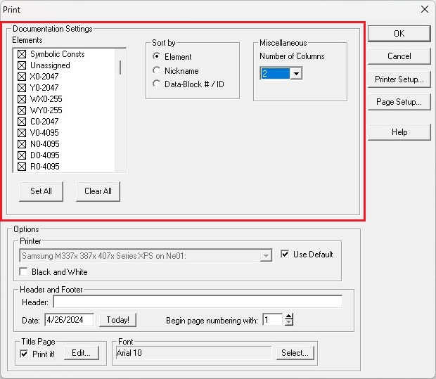
The Elements section selects which memory blocks, heap items, and structures, that have been given Element Documentation (Nickname / Extra Info / Description) to include in the print. The default configuration will include all ranges, all heap items, and all user-defined and system-defined structures. Use the Set All and Clear All buttons to include all of the potential Elements or include none of the Elements respectively.
The Sort by group selects how the Elements in the Print will be sorted:
-
Element will generate the print sorted alphabetically by Element.
-
Nickname will generate the print sorted alphabetically by Nickname.
-
Data-block # / ID will generate the print sorted by Block number or Heap ID number.
The Miscellaneous group contains the Number of Columns ( 2 - 6 ) to appear on each page. Note: as the number of columns increase, the amount of space allotted to each column decreases, and documentation fields that are too long, will not be wrapped; they will be truncated.
Print and Print Preview for Cross Reference View
When Print or Print Preview is invoked from the Cross Reference View, the top section of the dialog contains options used to generate a hard copy of the Element usage in the project. Cross Reference View has two modes: Xref mode which shows where each element is used, and Usage mode which shows which PLC memory elements are used. Print can generate output from either or both modes.
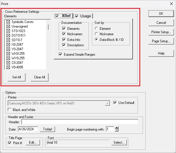
The Elements section selects which memory blocks, heap items, and structures fields, that have been used in the project to include in the print. The default configuration will include all ranges, all heap items, and all user-defined and system-defined structures. Use the Set All and Clear All buttons to include all of the potential Elements or include none of the Elements respectively.
If the XRef tab is enabled the following options are used:
The Documentation group defines which of the project documentation to include on the printout.
Check Elements to include the element name (e.g. X0, R0, etc.).
Check Nicknames to include element nicknames (e.g. MotorStart, Pump27, etc.).
Check Extra Info to include element wiring info (e.g. Blue - 10).
Check Descriptions to include element descriptions (e.g. This is the Motor Starter ).
The Sort by group selects how the Elements in the Print will be sorted:
Element will generate the print sorted alphabetically by Element.
Nickname will generate the print sorted alphabetically by Nickname.
Data-block # / ID will generate the print sorted by Block number or Heap ID number.
If Expand Simple Ranges is checked, for instructions using ranged elements, an entry will be generated for each element in the specified range; if unchecked, only one entry will be generated for entire range.
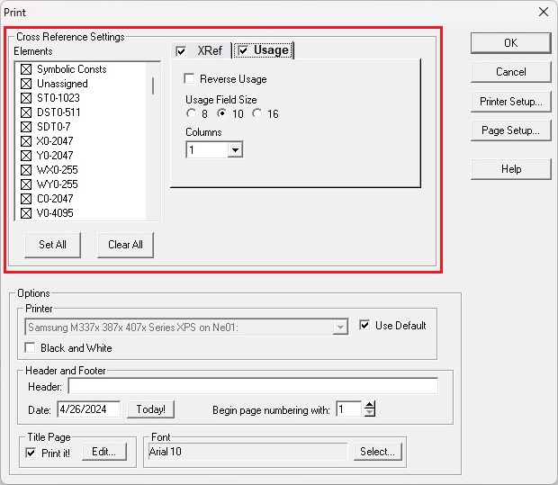
If the Usage tab is enabled the following options are used:
If Reverse Usage is unchecked, the range of elements will be displayed Low to High from left to right; if checked, the range of elements will be displayed High to Low from left to right.
The Usage field Size group selects how many successive elements will be displayed , either 8, 10, or 16.
The Columns selection group specifies how many columns of Usage data to put on each page, either 1, 2, 3, or 4 columns.
The Options group contains more print settings.
The Printer group selects the printer to use.
Use Default will print to the default printer selection on the PC that is displayed in the list. To select a different printer uncheck this option and use the down arrow in the Printer field to select from among the printers that are available on the PC.
Checking the Black and White option will force the printout to black and white instead of colors that match those used in the Do-more Designer programming software.
The Header and Footer group optionally adds a line of text to the top and bottom of each page in the printout.
Header is the text to add to the top and bottom of each page.
Date is the date to put on the printout.
Click Today! to retrieve the current date from this computer.
Begin page numbering with is the first page number to use on the printout.
The Title Page group optionally includes the Title Page
Check Print it! to include the Title Page in the printout.
Click the Edit ... button to invoke the Title Page Editor.
The Font Group selects the font to use when generating the printout
Click the Select... button to display a list of the fonts loaded on the computer and select the font to use.
Click the OK button to initiate the Print or Print Preview operation using the settings currently displayed.
Click the Cancel button to exit the dialog without generating the print preview..
Click the Printer Setup... button to invoke the setup dialog for the currently selected printer.
Click the Page Setup... button to invoke a dialog to set the margins for the printed page.
Click the Help button to invoke the main help system.
See Also:
Print / Print Preview