Topic: DMD0356

Memory View
The Memory View is a Dockable![]() A Dockable window is one that can be connected to the sides, top, or bottom of another window.
Docking is done by clicking the mouse in the colored portion of the top bar of the window and dragging it toward the edge of the contain window. As it approaches the containing window, a reverse video block will appear, showing how the docked window will appear in its docked form. and Floatable
A Dockable window is one that can be connected to the sides, top, or bottom of another window.
Docking is done by clicking the mouse in the colored portion of the top bar of the window and dragging it toward the edge of the contain window. As it approaches the containing window, a reverse video block will appear, showing how the docked window will appear in its docked form. and Floatable![]() This window can "float" on the screen and remain functional while being unconnected to an edge of a containing window.
Floating a window is done by clicking the mouse in the colored portion of the top of the window and dragging it away from the edge, As the window is dragged away, a reverse video block will appear, showing how the window will appear in it's floating form. utility for monitoring and changing the contents in memory locations and structure fields in a Do-more CPU. This utility is only available when Do-more Designer is online with the CPU.
This window can "float" on the screen and remain functional while being unconnected to an edge of a containing window.
Floating a window is done by clicking the mouse in the colored portion of the top of the window and dragging it away from the edge, As the window is dragged away, a reverse video block will appear, showing how the window will appear in it's floating form. utility for monitoring and changing the contents in memory locations and structure fields in a Do-more CPU. This utility is only available when Do-more Designer is online with the CPU.
Using the Memory View, user can view the current value in any memory location or structure field in the CPU. Users can enter constant values in any of the Bit memory locations, Integer and Real memory locations, Strings, and structure fields.
A single Memory View can only display and edit the values of a single memory block, or a single block of structures. Do-more Designer can support up to 100 concurrent Memory Views. To create a new Memory View, click the Memory icon on the Online toolbar, or select Debug -> New Memory View from the Menu bar.
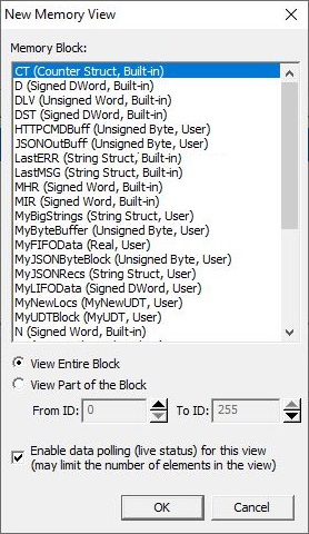
Memory Block contains a list of all the Bit, Numeric and String memory blocks, and the system-created and user-created blocks of structures from the current Memory Configuration.
-
View Entire Block adds each element of the memory block, or each field of the selected structure to the Memory View.
-
View Part of Block allows the user to specify a range of the elements in the memory block to be added to the Memory View.
From ID: is the first element in the range of the selected block.
To ID: is the last element in the range of the selected block.
Check Enable Data Polling (live status) for this view to allow the Read Only (Enable Automatic Reads) option to function for this view.
There is a limit on the amount of data that can be read and written from a single Memory View. The actual limit is dependent on the memory type of the data being accessed. If you exceed the limit you will see a message similar to this:
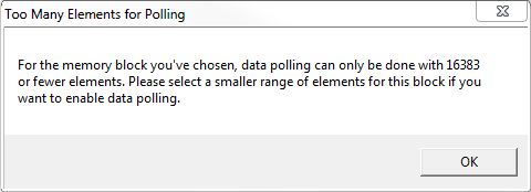
Click OK to return to the New Memory View setup dialog where you can either select a smaller number of elements to manage in this Memory View, or uncheck the option to turn on Data Polling.
The Memory View Display
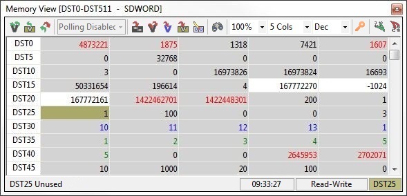
The Memory View uses color-coded display of the values to indicate various information about the values of the individual Elements in the data block. They are as follows:
A cell's background color of Olive Green indicates the current cursor position.
A cell's background color of Red indicates the text in that cell IS NOT VALID for the given data type and format.
Note: hover the mouse cursor over a cell with a Red background to see the error message in the popup tooltip.
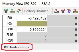
A cell's background color also indicates the current Cross Reference state for the Element.
White means the Element IS USED in the current project.
Gray means the Element IS NOT USED in the current project.
As the edit cursor and the mouse cursor move over the cells in the view, the Used / Not-Used state is also shown in the lower left corner of the Status Bar as shown below:
A cell's foreground color indicates the state of the value that is currently displayed for each Element.
Black for values that DID NOT CHANGE when the last read operation was performed.
Red for values that CHANGED when the last read operation was performed.
Blue for values that have been edited in the Memory View but NOT WRITTEN TO the PLC.
Green for values that have been edited in the Memory View and written to the PLC but have NOT BEEN READ BACK FROM the PLC. Use any of the Read operations to verify that the values remain at the edited / written value.
If the text in the cell is BOLD regardless of the foreground color, this indicates the Element was FORCED the last time its value was read from the PLC. A forced element's value cannot be changed by the Memory View, it can only be changed by using the Configure Force utility.
Keystrokes and Mouse Actions
The keystrokes and mouse actions within the Memory View are optimized for quick data entry of constant values into memory locations.
Navigating Within the Memory View
LEFT, RIGHT, UP, and DOWN arrow keys move the cursor one cell in the direction of that arrow.
TAB will move the cursor one cell to the right. If the cursor is on the last column of the view the cursor will move to the first column of the next row.
SHIFT+TAB will move the cursor one cell to the left. if the cursor is on the first column of the view the cursor will move to the last column of the previous row.
HOME will move the cursor to the same column in the first row in the view.
END will move the cursor to the same column in the last row in the view.
Multiple ways to Begin an Edit Session for a Cell
Double click with mouse on a cell.
or Use the keyboard to begin entering a new value at the current cursor location.
or SPACE will begin an edit session with the entire value in the cell at the current cursor location.
Editing the Value in a Cell
UP arrow will increment the current value in the cell by one .
DOWN arrow will decrement the current value in the cell by one .
LEFT and RIGHT arrows will move the caret one digit to the left and right respectively within the current value.
DELETE will delete one digit to the right of the caret.
BACKSPACE will delete one digit to the left of the caret.
Using a Click & Drag with the mouse, or SHFT+Right Arrow or SHFT+Left Arrow will select the individual characters of the value in a cell.
Double-Click will select all of the contents of the cell.
CTRL+C will copy the selection to the clipboard.
CTRL+X will cut the selection from the cell and place the selection in the clipboard.
CTRL+V will paste the clipboard contents into the cell at the current cursor location.
Ending the Edit Session
TAB will accept the current value in the cell, move the cursor to the cell in the next column to the right and begin editing the value in that cell.
SHIFT+TAB will accept the current value in the cell, move the edit cursor to the cell in the previous column to the left and begin editing the value in that cell.
ENTER will accept the current value in the cell and leave the edit cursor on that cell.
A mouse click in another cell will accept the current value in the cell being edited, then move the edit cursor to the cell that was clicked on.
ESCAPE will abort the edit session and leave the original value of that cell intact.
Note: at the conclusion of an edit session, the accepted value in a cell is NOT written to the PLC until one the write operations is performed. The exception is having Auto-Write Mode is enabled.
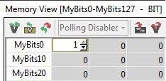
Entering constant values into Bit memory locations.
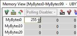
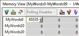
Entering constant values into Numeric memory locations.
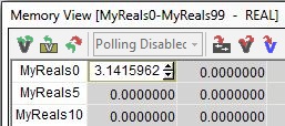
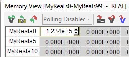
Entering constant values into Real memory locations.
Real format:
Exponential format:
 .
.
Entering a String Literal Zero or more characters enclosed in double quotes, as in "hello", and may include both simple escape sequences (such as \t for the tab character) and hexadecimal data (such as 0xAA). into a String Element.
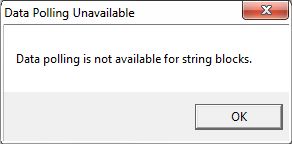
Memory View does not allow Automatic Reads for Strings. The Memory View will display the following message when the it is created with a String data type:
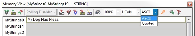
If the text to be entered into the String contains only displayable ASCII characters then ASCII display format is the proper choice.
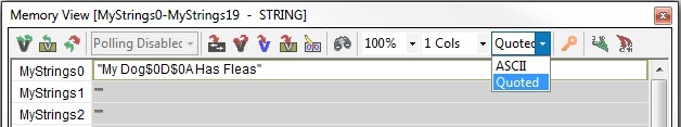
If the text to be entered in the String contains any non-displayable ASCII characters, for example <CR><LF>, or $N, or 0x0D0A then select the Quoted display format so that the control characters can be displayed properly.
Any attempt to close the Memory View when changes have been made to any of the values in the Memory View but those changes have not been written to the PLC, you will see a message similar to the one below that asks what to do with the unwritten changes:
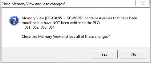
Yes closes the Memory View but does not write the pending changes to the PLC.
No closes the message box and returns to the Memory View so the pending changes can be written to the PLC.
Read Operations
The Read operations are used to refresh the data values displayed in the Memory View by reading new values from the connected PLC. The last time any of the Read operations was successfully executed will be displayed in the Status bar of the Memory View.
Read All

Will read the values for every location in the Memory View. Notice that values that changed from the last read will be displayed in RED, all unchanged values will be in BLACK.
Read Current Item

(right-click-> Read the Element from the PLC) - will read the value for the location where the cursor is located in the Memory View.
Toggle Read-Only

When ON, this will prevent editing any of the values in any of the cells in the Memory View and enable the Poll Rate selection. The current state (Read-Write or Read-Only) is also shown on the Status bar of the Memory View. The default state of new Memory Views can be set to Read-Write or Read Only on the Options tab as shown in the Setup section below.
Poll Rate

Enabling one of the Poll Rate selections will cause the Memory View to automatically begin reading the values for all of the Elements in the Memory View. The default selection is Polling Disabled; you must select one of the other poll rate options (1, 2, 5 or 10 Seconds) to cause the Automatic Read All operation to begin executing at the selected poll rate.
Note: Automatic Reads are not valid for Memory Views containing Stings.
Note: When Automatic Reads are enabled all of the Write operations will be disabled.
Any attempt to execute any of the read operations when changes have been made to any of the values in the Memory View but those changes have not been written to the PLC, you will see a message similar to the one below that asks what to do with the unwritten changes:
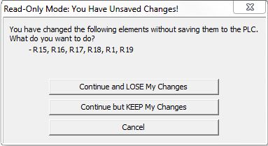
Continue and LOSE My Changes executes the read operation and overwrite any edited value in the Memory View with the value from the PLC
Continue but KEEP My Changes executes the read operation but do not overwrite the edited value in cells that have not been written to the PLC.
Cancel aborts the read operation.
Write Operations
The Write operations are used to send the values displayed in the Memory View to the connected PLC. Structure fields in UDTs can be set to read-only; all of the write operations will skip over structure fields that have been marked as read-only. When writes are enabled and the cursor moves onto a field that is read-only, the status bar will display 'Read-Only'.
Enable Automatic Writes

Enabling this feature will cause the Memory View to write the edited value for a cell when either the TAB or ENTER key is pressed (notice the value is displayed in Green). If you leave the editor with a mouse click to a different cell the edited value will NOT be written (notice the value will be displayed in Blue).
The following confirmation is displayed before Automatic Writes is enabled.
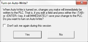
Enabling the Don't ask me again during this session option will prevent the dialog from being displayed on subsequent attempts to enable the Automatic Writes during this online session.
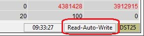
When Automatic Writes are enable the Status bar will display the following:
Write Entire View

Will write the value for every memory location in the Memory View to the PLC. Note: if the Memory View is working with structures, all of the fields of the structure will be written, even if not all of the structure fields are being displayed in the view, because the Number of Columns selection is set to Short or Long, instead of All.
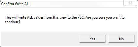
The following confirmation is displayed before each execution of a Write Entire Block operation:
Write Edited Elements

Will write ONLY the values that have been changed since the last Write operation was executed.
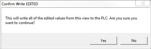
The following confirmation is displayed before each execution of a Write Edited Elements operation:
Write Current Element

(right-click-> Write the Element to the PLC) will write ONLY the value for the cell where the current edit cursor is located.
The following confirmation is displayed before each execution of a Write Current Element operation:
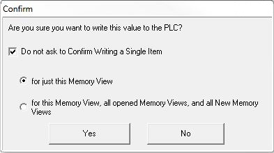
Enabling the Do not ask to Confirm Writing a Single Item option will prevent the dialog from being displayed on subsequent execution of the Write Selected Element while this Memory View is in use.
Write Specific Structure Fields (only for structures)

If the Memory View is displaying User-defined or System-defined structures, this option will write only the structure fields that are selected on the following dialog. This dialog will display all of the writable fields in the structure in the left pane. For each file that you want to write, highlight the fields - select multiple fields with CTRL+ left mouse - then click the Add button, and the selected fields will move to the right pane. If you want to write all of the fields of the structure, click Add All to move all of the fields to the right pane. Remove and Remove All will return the appropriate fields from the right pane to the left. Note: if the structure contains fields that are unions, you must resolve that issue as well, see the section below for handling unions.
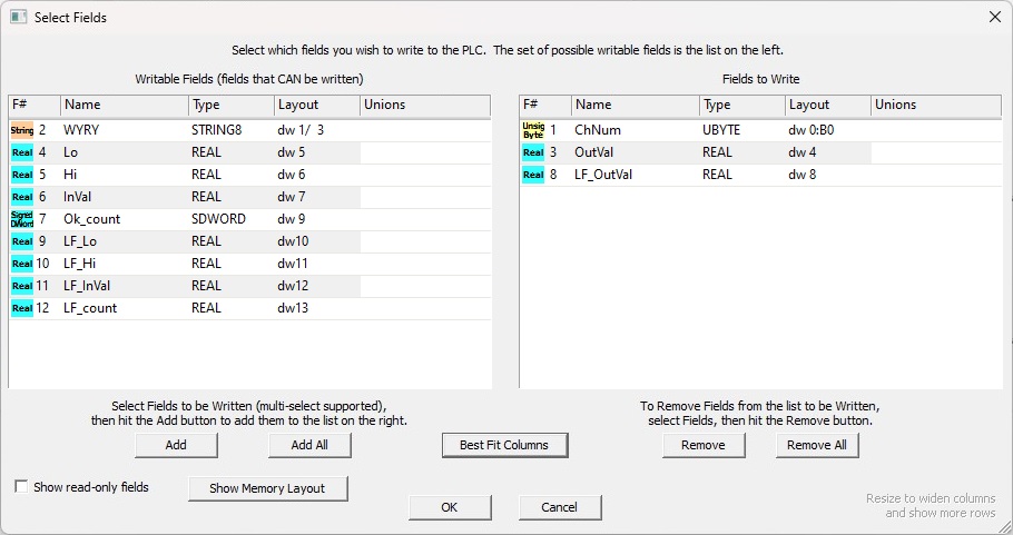
Enable Show read-only fields to display any fields in the structure that are not writable.
Click the Show Memory Layout button to display how the fields in the structure are mapped in the structure. This is particularly useful if the structure contains unions.
Click the Best Fit Columns button to optimize the column widths based on the fields widths.
Handling Unions in Structures
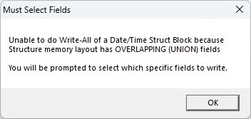
If the Memory View is displaying User-defined or System-defined structures, AND those structures have fields that were created as unions, you must specify which of the union field to write during a Write All or Write Specified Fields operation. If a structure has one or more union fields, you will first see the following message box followed by a subsequent dialog which will display the fields that were created as unions in the structure.
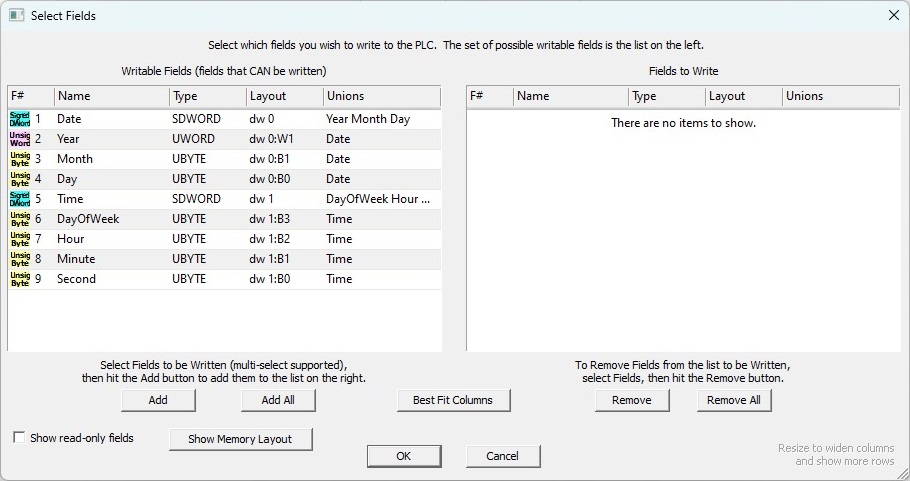
In the example below:
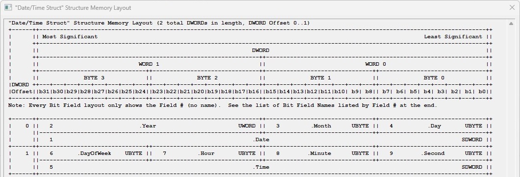
Field #1 (Date- Signed DWord) was created in union with fields #2 (Year - Unsigned Word), #3 (Month - Unsigned Byte), and #4 (Day - Unsigned Byte).
Field #5 (Time- Signed DWord) was created in union with fields #6 (DayOf Week - Unsigned Byte), #7 (Hour - Unsigned Byte), #8 (Minute - Unsigned Byte), and #9 (Second - Unsigned Byte).
To select the Date and Time fields (instead of their union fields), select those two fields in the left pane and click the Add button to move them to the right pane, as shown below.
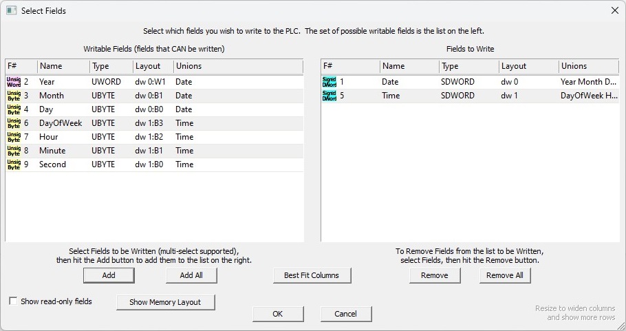
Clicking the Ok button will process the Write All using the fields selected above. Subsequent Write All operations will reopen this dialog and retain the selections previously made. At this point, you can change the selections if needed, or simply click the Ok button to process the operation.
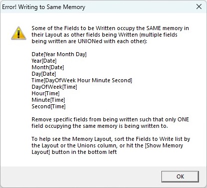
If the selections made have NOT handled all of the unions in the structure, a dialog similar to the following is shown with details on which fields still need to be handled.
Clear All Data in View

Will clear all of the values in Memory View. If the values or structure fields are Bit or Numeric they will be set to 0. If the values or structure fields are Strings they will be cleared.
Note: this DOES NOT write the cleared values to the PLC - notice the cleared values are in Blue - only the values in the Memory View itself are cleared. You must still use one of the Write operations to send the cleared values to the PLC if needed.
Setup Operations
Goto

Locate the specified memory location in the Memory View and move the edit cursor to that cell.
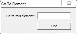
Go To This Element: enter the element to search for the click the Find button to perform the search. If the search is successful the view will move the edit cursor to the cell that contains the Element. If the search is unsuccessful it's mostly likely because the Element type is wrong or the Element is out of range for the Memory View.
Zoom Level

Sets the size of the data values displayed in the Memory View. To change the Zoom Level, select one of predefined options in the drop-down list (500%, 300%, 200%, 150%, 100%, 90%, 75%) or type in any percentage value between 50 and 500.
Number of Columns
If a numeric memory block is selected, this is the number of columns of Elements in the Memory View. When the Memory View is initially created it will have 5 columns for data blocks that are numbered in decimal, and 4 columns for data blocks that are numbered in octal. To change the number of columns, select one of the predefined options in the drop-down list (1, 2, 5, 10, 15, 20, 25, 30), or enter a value then press RETURN.

If the memory selected is a structure, this list will contain Critical (will display only the most commonly used fields), Useful (will display the commonly used fields), and All (will show all of the structures fields). Note: after changing the number of columns to display, clicking the |<- A ->| icon to the right o f the Number of Columns selection will 'auto-fit' the column widths to the current width of the Memory View.

Display Format

When the Memory View is showing values from a numeric data block, this selects data format of the values that will be used to display and edit all of the Elements in current that view.
For Bit Elements the format selection is only decimal (0 or 1).
For Numeric Elements the format selections are Decimal, Hexadecimal (0x...), Octal (0...), Binary (xxxx_xxxx_xxxx_xxxx), ASCII (my text), and Swapped ASCII (my text).
Note: ASCII format is especially useful when a Numeric Data Buffer is used to store text for use by the HTTPCMD, JSONBUILD, and JSONPARSE instructions.
For Real Elements the selections are Real (1.234) and Exponential (1.234E+000).
For String Elements the selections are ASCII (my text) and Quoted ("my text").
Use ASCII if the text contains only displayable characters. Use Quoted if the text contains any non-displayable characters, for example <CR><LF>, or $N, or 0x0D0A.

When the Memory View is showing values from structures, this selects data format of the values that will be used to display and edit all of the Elements in the column where that value is shown.
Native (or Smart Native) is the default selection for structure fields because the data type of the field is known through the structure definition.
Decimal, Hexadecimal (0x...), Octal (0...), Binary (xxxx_xxxx_xxxx_xxxx).
Month (0 = January, 1 = February, 2 = March, 3 = April, 5 = May, 6 = June, 7 = July, 8 = August, 9 = September, 10 = October, 11 = November, 12 = December)
Day of Week ( 0 = Sunday, 1 = Monday, 2 = Tuesday, 3 = Wednesday, 4 = Thursday, 5 = Friday, 6 = Saturday)
Seconds (d/h/m/s) (DD/HH/MM/SS)
1970 Epoch (11-JAN-1970 THU 00:00:00)
Time (SUN 00:00:00)
Date (MM-DD-YYYY)
ASCII (my text)
Swapped ASCII (my text)
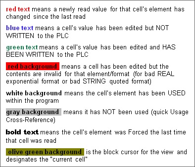
Color Key

Clicking the Show Color Key button will open the following dialog which details the foreground and background colors used by Memory View to relay state information:
View Memory Layout ( for structures )

Will open the current structure in a view that contains a graphical depiction of how the memory is packed into the structure, similar to the one shown below :
Import Data

Import Data will read in values from an external CSV (comma separated variables) file that has been previously exported from a Memory View, or exported from the Memory Image Manager, or exported by the Export Memory Data utility, or one that has been manually created with the appropriate format. Refer to the Import Memory Data utility for details on the required format.
Only data from the import file that is from the same range of the same memory block that this Memory View is using will be imported. Any time there is a mismatch between the range in the Memory View and the range in the import file a message box will be displayed with details about exactly how much (if any) of the data was imported.
Refer to the Import Memory Data utility for details on the required format.
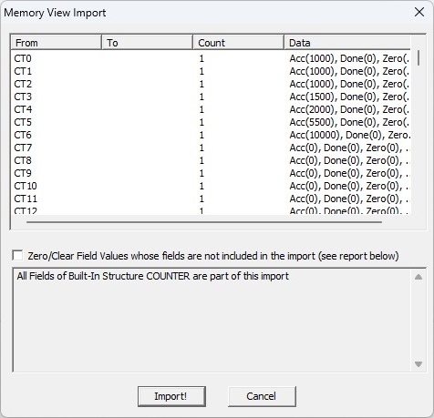
Enable the Zero / Clear Fields values whose fields are not included in the import (see report below) option to clear the values of fields in the structure that do not have a value specified in the import file.
Export Data

Store the current value for every Element in the Memory View in an external file in CSV (comma separated variables) format. After you specify the export file name, the following dialog opens where you can specify the format of the data in the export file. The exported file will be formatted the same way as the export file from the Export Memory Data utility.
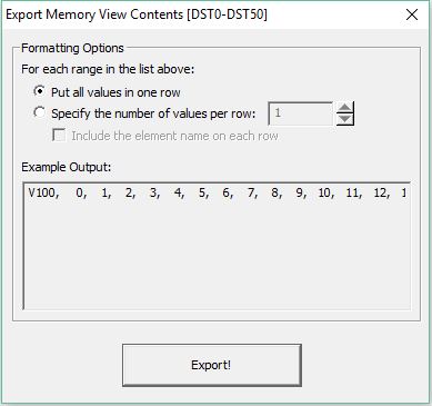
Put All Values in One Row will output all of the values for each range in a single row.
Specify the Number of Values per Row will output the specified number of values for each range in a single row.
Include the Element Name on Each Row specifies whether or not to include the name of the first element on each row.
if enabled each row for each range will begin with start with name of the first element on that row.
if disabled the first row for each range will begin with start with name of the first element on that row and subsequent rows will contain only the consecutive values in that range.
Example Output: will display a portion of the export text using the selections made above.
Click the Export! button to proceed. A Save As dialog will open where the folder and file name of the export file can be entered.
----------------------------------------------------------------------------------------------------------------------------------
If the Memory View contains a System-defined Structure or a User-defined Structure, the following dialog is opened that allows you to specify which of the structure's fields to export, and what display format to use for those fields.
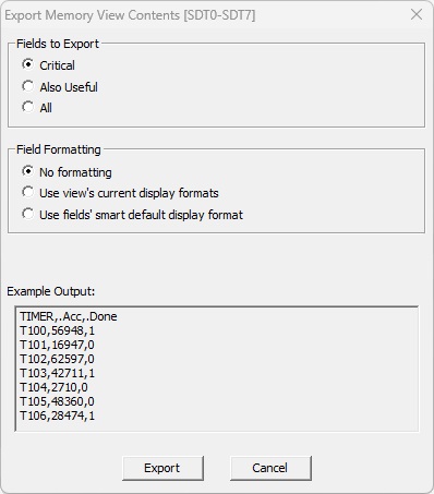
Fields to Export selects how many of the structure's fields to include in the export as specified by the structure's Level Status:
Critical will include the fields marked as 'Show in Short and Long Format'
Also Useful will include the fields marked as 'Show in Long Form Only'
All will include all of the structure's fields in the export.
Field Formatting selects the display format used when exporting the field's data:
No Formatting will use the system's default format based on the data type of the value in the fields.
Use View's Current Display Format will use the format specified in the Memory View.
Use Field's Smart Display Format will use the format specified in the structure's definition.
Example Output: will display a portion of the export text using the selections made above.
-----------------------------------------------------------------------------------------------------------------------------------
Once the Export completes successfully, the final dialog is opened that allows the following:
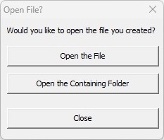
Open the File in the application associated with the export file's extension.
Open the Containing Folder where the export file was written in Windows Explorer.
Close this dialog.
If the width of the Memory View is narrower than the toolbar, a chevron ( » ) will appear at the end of the toolbar. Click the chevron to open a drop-down list that contains all of the toolbar buttons that would not fit on the toolbar at its current width. Refer to the image below:
![]()
Set Default Options
Right-click over the Memory View and select Options... or select View -> Options to open the Memory View tab of the Options dialog where you can set the default selections for new Memory Views.

Position for New Views is where all new Memory Views will initially be docked:
- Floating (default) means the center of the Do-more Designer application window.
- Dock on Left means docked on the left edge of the Do-more Designer application window.
- Dock on Bottom means docked on the bottom edge of the Do-more Designer application window.
Default Display Format is specifies the default data format of the values that will be used for all of the Elements in new Memory Views:
For INTEGER elements the default format selection can be Decimal, Hexadecimal (0x...), or Octal (0...).
For REAL elements the default selection can be Real (1.234) or Exponential (1.234E+000).
For STRING the default selection can be ASCII (my text) or Quoted ("my text"). Use ASCII if the text contains only displayable characters, or use Quoted if the text contains any non-displayable characters, for example <CR><LF>, or $N, or 0x0D0A.
Number of Columns for New Views is the default number of columns of Elements in new Memory Views.
- Default 5/4 specifies 5 columns for data blocks of decimal numbers and 4 for data blocks of octal numbers.
- Custom allows you to enter a value from 1 to 32.
Safety specifies the default enabled / disabled state of confirmation dialogs:
If Ask for Confirmation when Writing a Single Item is enabled, the Confirm Write message box will be displayed when writing a single element to the PLC.
Default Mode specifies the initial mode for New Memory Views:
- Read Only means reading is enabled and writes will be disabled for new Memory Views.
- Read / Write means both reading and writing will be enabled for new Memory Views.
See Also:
Memory Image Manager for Retentive Memory