Topic: DMD0065

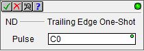
ND - Trailing Edge One-Shot
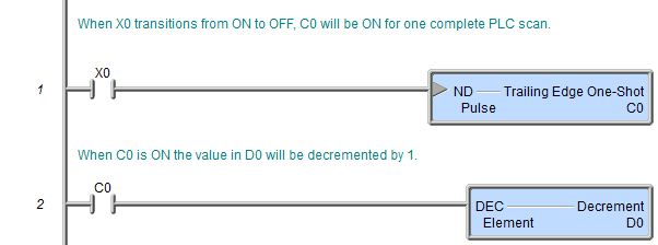
When the input logic generates an ON to OFF transition, the Trailing Edge One-Shot (ND) instruction will turn ON the specified bit location for one complete scan then it will be turned OFF.
Note: use the Leading Edge Powerflow Modifier to generate a single one-shot event for multiple output instructions without requiring the use of a bit memory location.
instruction Inputs:
This instruction has one ladder logic input.
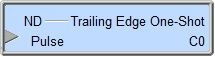
The gray triangle at the right end of the input leg indicates this input is edge-triggered, meaning that each time the instruction's input logic transitions from ON to OFF, the specified bit location will be ON for one complete scan.
Parameters:
Note: Use the F9 key or click the 'three dot box' at the right edge of the parameter field to open the Default Element Selection Tool (the Element Picker or the Element Browser) or use the Down-Arrow key (Auto-Complete) on any parameter field to see a complete list of the memory locations that are valid for that parameter of the instruction.
Pulse - specifies the bit memory location to use. This can be any writable bit location.
See Also:
Related Topics:
(CONTACT) - Negative Differential (One-shot Falling) (STRND / ANDND / ORND)
(CONTACT) - Positive Differential (One-shot Rising) (STRPD / ANDPD / ORPD)
(CONTACT) - Leading Edge Powerflow Modifier (ANDPDPF)
(CONTACT) - Trailing Edge Powerflow Modifier (ANDNDPF)
(CONTACT) - Invert Powerflow (NOT)
Example: