
EBC/EBC100 FAQs
(Last
Update: 09-Aug-2022, EBC FAQ0097)
EBC FAQ0001
28-May-2002
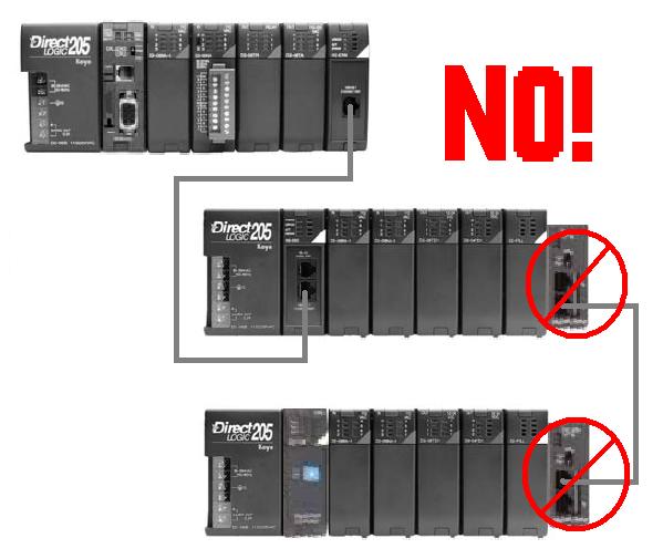
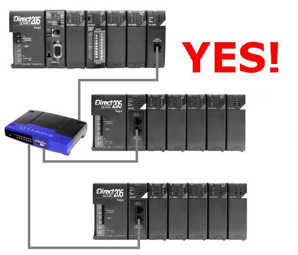
Q: Can I add remote I/O connections to my EBC rack?
A: No. Instead you should use multiple EBCs for the same effect.
EBC FAQ0002
10-Jul-2002
Q: Does EBC support Modbus TCP?
A: The EBC models do not (H2-EBC; H4-EBC; T1H-EBC), but the
EBC100 models do (H2-EBC100; T1H-EBC100)
EBC FAQ0003 (see also
ERM FAQ0001)
11-Jul-2002
Q: ERM Workbench is not reporting errors when the analog output
cards in the EBC rack are missing +24Vdc supply.
A: Facts Engineering (the designer of the analog cards) says that
the cards themselves do not report errors regarding the absence of
their +24Vdc supply. Therefore the EBC doesn't see them, and
subsequently neither does the ERM or the Workbench software.
EBC FAQ0004 (see also NetEdit FAQ0011; ECOM
FAQ0034; EDRV FAQ0008; ERM FAQ0024; PBC FAQ0015)
07-Jan-2015
Q: Getting various errors when attempting to update the
booter/firmware for my EBCs, ECOMs, EDRVs and ERMs.
A: First make sure you isolate the device from all other tasks
(i.e. put the PLC in the STOP mode; stop HMI; isolate from busy
network traffic). Secondly, make sure you are using the latest version
of NetEdit3 which can be downloaded for free here:
http://www.hosteng.com/SW-Products/NetEdit3.zip
Here are some common problems experienced:
- (1) After Rescanning, the
booter/firmware version doesn't change -
NetEdit is probably getting an error that is not getting reported.
Upgrade to the latest NetEdit (i.e. >v3.4). If this doesn't work
then report the error to us (support@hosteng.com)
and we can send you ETHER32.EXE which should do it.
- (2) "Error booting to booter" - You are probably using the old ETHER32.EXE utility. It
is much easier to utilize the latest NetEdit3 to accomplish updates.
It has a fully integrated firmware/booter update facility as well as
"live update" feature to retrieve the latest firmware/booter files
from our website.
- (3) "Error! Error 32774 from
DownloadBinFile!" - This error 32774 is
sometimes indicated as "Error 0x8006" and simply is a general
timeout message. This simply means that NetEdit3 cannot talk to the
device in a consistent manner (i.e. uninterrupted). Some things that
can cause this:
- The network could be too busy, therefore isolate this device
and try again.
- The WinXP firewall could be turned on. If so you must do one
of the following:
(1) Turn the firewall off, or
(2) Create an exception for NetEdit3.EXE
application, or
(3) Create an exception for port #0x7070
(28784) for both TCP and UDP protocols. which is the port number
that all of our Ethernet devices use for communication.
- (4) "Error 216" - This error means there were severe problems with either
writing the firmware to the device, or verifying what was written.
Usually if you get this error, it leaves the device in the booter
state (i.e. the red ERR light is flashing). In most cases all that
is needed is to make sure you isolate the device from all other
tasks (as mentioned above), and try the update again.
- (5)
"Error! Error 212 from DownloadBinFile!" - This error
212 means the booter in the device you are trying to update is too
old to recognize the "go-to-booter" command coming from NetEdit3.
There are two possible solutions:
- Use NetEdit v2.x or earlier to update the booter for your device,
or...
- Obtain a copy of the command-line program called ETHER32.EXE from
us (support@hosteng.com) to
update the booter for your device.
- (6)
"Error -2 from DownloadBinFile!" - This is very similar to
(5) above with the same
solutions.
- (7) The module loses
firmware or its IP address - Use Restore Factory Defaults
option (e.g. with ECOM100s) to clear the memory contents and try
firmware update again. To prevent future firmware corruption, check
your cabinet and the surrounding area for severe noise sources, such
as unsuppressed solenoids. Improperly wired drives are another
common source of severe noise. See Automation Direct AN-MISC-032
for guidance on adding suppression to solenoids.
EBC FAQ0005
06-Jan-2003
Q: When attempting to update the firmware for an H2-EBC, get
"Error 206 - Open file error."
A: This error is displayed when the program can't find the name
of the .bin file that was entered on the command line. This is usually
due to typing in the name of the .bin file incorrectly. Correct the
filename, or . .
Download the ERM Workbench software and use it to update the booter
and firmware of the EBC.
EBC FAQ0006 (see also
NetEdit FAQ0003, ERM FAQ0003, EDRIVE FAQ0004)
09-Sep-2009
Q: NetEdit sees ERM, EBC and EDRV, but ERM Workbench gets error
"ERM not found" when trying to write the configuration to the ERM.
A: Downloading the latest version of ERM Workbench may remedy
this problem; especially if you are using the ERM Workbench Wizard.
You should download at least ERM Workbench v1.1 Build 26. Otherwise
here are some things to try:
- Make sure NWLink IPX protocol is
loaded for your PC's NIC (see EBC FAQ0057 for
installing protocols).
- Make sure NWLink IPX protocol is
disabled (unchecked) for any other network connections other than the
one you will be using.
- Make sure your PC's NIC is not
"Bridged" but only "Enabled." (My Network Places --> Properties).
- Make sure you have no other "Bridged"
connections "Enabled" in your list of LAN Connections. (My Network
Places --> Properties).
- Make sure you only have a single LAN
Connection and not multiple connections. (My Network Places -->
Properties).
- Make sure your Internal Network
Number is set to "00000000." (My Network Places --> Properties
--> LAN Connection --> Properties --> General tab -->
NWLink IPX protocol --> Propterties button).
- Make sure you have "QoS packet tagging"
disabled. (My Computer --> Properties --> Hardware tab -->
Device Manager button --> Network adapters --> (your NIC's name)
--> Properties --> Advanced tab --> 802.1p QOS).
EBC FAQ0007 (see also
ERM FAQ0004)
07-Jan-2003
Q: Can an EBC's (hooked to an ERM) serial port be used for HMI
devices?
A: No, ERM doesn't support serial-port comm on the EBC. ERM100
& EBC100's will have serial port support, however.
EBC FAQ0008 (see also
DL Plus FAQ0001)
14-Jan-2003
Q: Can DL Plus software talk directly to EBCs?
A: DL Plus only allows Lookout to talk directly to ECOMs.
However, since Lookout has an OPC Client, it could talk directly to
KEPDirect EBC I/O Server software which talks directly to EBCs.
EBC FAQ0009
21-Jan-2003
Q: Is the KEPDirect software TCP/IP or UDP/IP?
A: UDP/IP, because the EBC only talks UDP/IP.
EBC FAQ0010 (see also
ERM FAQ0005, WinPLC FAQ0001)
22-Jan-2003
Q: Does the WinPLC allow for an ERM?
A: Yes. The WinCE-only version can have up to 6 ERMs (due to
power budget limitations) and each ERM supporting as many as 16 EBCs.
However if the WinPLC you are using is a Think&Do version you are
limited to only 1 ERM and that ERM can only have 1 EBC.
EBC FAQ0011 (see also
ERM FAQ0006)
21-Jan-2003
Q: Have DL260 using 2 ERMs on 2 separate networks. Worked for a
season. Now the second ERM fails if more than 2 EBCs are hooked to
it.
A: Since the system worked good for a while, then something
obviously changed. Check network hardware (like hubs).
EBC FAQ0012 (see also
ERM FAQ0007, SDK FAQ0001)
29-Jan-2003
Q: How do you determine what state the outputs will go to if comm
is lost on the EBC?
A: If using the SDK, this can be set with the subroutine
HEIWriteSetupData. If using ERM WorkBench the watchdog has a timeout
value and by default it is set to freeze outputs if comm is lost..
However, you can also set it to disable all outputs if watchdog fires.
EBC FAQ0013 (see also
ERM FAQ0008)
11-Jun-2002
Q: Error codes for ERM and EBC are hard to understand and
incomplete.
A: Error codes have been added to the ERM Workbench and the ERM
manual with explanations of possible causes.
EBC FAQ0014 (see also
CTRIO FAQ0012, PBC FAQ0004, WinPLC FAQ0003)
06-Feb-2003
Q: CTRIO Workbench indicates that the CTRIO module is in "Startup"
mode and all of the configuration parameters are grayed out.
A: "Startup" mode indicates that CTRIO Workbench cannot
successfully communicate with the CTRIO. The problem is not between
CTRIO Workbench and the CPU, the problem is between the CPU and the
CTRIO itself. Communication across the backplane is failing. Here are
some known causes of this:
- The CTRIO is in the slot adjacent to
the CPU (slot 0) and you are using a D2-240, D2-250 or D2-260 CPU. You
must move it to another slot.
- You are using CTRIO Workbench v1.1
with a CTRIO that has firmware version 2.0.1 or later. Update your
Workbench.
- You are using CTRIO Workbench v1.1
and starting it from DirectSOFT. Either start it from DS Launch or
upgrade CTRIO and CTRIO Workbench.
- The PLC has old firmware. This Product
Advisory details the revision levels required.
- The PLC power is OFF.
- You have a DL205 in a "-1" base (the
ones that have the expansion I/O connector on the right side), and you
have an H2-EBC, H2-WinPLC or H2-PBC that has not been modified to work
in these new bases.
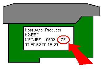
H2-EBC less than 7F (7F and 8F work)
H2-EBC-F less than 1F (1F works)
H2-WPLC1, WPLC2 less than 4K (4K, 5K & 6K work)
H2-WPLC3 less than 1K (1K works)
H2-PBC less than 2D (2D works)
* - Revision meaning: "7F" means: "7" is
bare board revision. "F" the revision of the assembly drawing that we
are using to build the boards.
If you have older EBC, PBC or WinPLC hardware, you have two options to
get them updated:
- RMA them back to Automation Direct (a
part will be shipped immediately to you).
- Send them to Host Engineering (you
will have to wait on the part to be modified and shipped back).
EBC FAQ0015 (see also
HA-TADP FAQ0001; EDRIVE FAQ0001; ECOM FAQ0008; ERM FAQ0009; WinPLC
FAQ0004; EZ Ethernet FAQ0011)
07-Feb-2003
Q: Can the MAC address be changed?
A: The MAC address is burned into the ROM of the device and is
set just before it leaves the factory. There is no logical way for any
protocol to change this address. Host Engineering’s range for Ethernet
MAC addresses is 00.E0.62.xx.xx.xx.
However, there was a bug with the old
Ether32.EXE program that could change the MAC Address! If you use
Ether32.EXE to update the booter using TCP/IP protocol (i.e. use the
"/pi" option on the command line), then the MAC Address could be changed
by accident!
- If MAC Address gets changed by accident
in the above fashion, then you will have to ship the module(s) to Host
Engineering for repair.
- When updating the booter/firmware of
the EBC, EDRV, ECOM or ERM always use NetEdit instead of the outdated
Ether32.EXE.
EBC FAQ0016 (see also ERM FAQ0010; ECOM FAQ0009;
EDRIVE FAQ0002)
07-Nov-2012
Q: Can ERM Workbench be used to upgrade firmware on other Host
Ethernet devices (e.g. an ECOM)? And if so, how?
A: Older
versions of ERM Workbench (before v2.0) can be used in this manner. If
ERM Workbench is v2.0 or later, then this is not possible; instead NetEdit3 must be used.
If using ERM Workbench earlier than
v2.0:
- Open ERM Workbench
- Press the <ERM Workbench> button
at bottom left (skip using Wizard)
- Press the <2. Select Slaves…>
button at top right.
- Window at left shows ERM devices, but
there is a filter at the bottom: "All Devices." Pick this one.
- Now all Host Ethernet devices are
shown. Pick device of your choice and press <Upgrade
Firmware...> button. Follow instructions.
EBC FAQ0017 (see also
ERM FAQ0011)
19-Feb-2003
Q: What is the response time of an EBC?
A: This is a common question and has a very technical answer. It
is also a bit ambiguous because in any system that utilizes an EBC
there are several different asynchronous loops going on that
contribute to overall delay (or response time). What follows are 14
formulas for calculating worse-case response time for all module types
(Discrete IN, Discrete OUT, Analog IN, Analog OUT). Keep in mind, this
is not a scan time that you are calculating, but rather a response
time.
A scan time is generally a constant (like
that of a PLC). Since there are several asynchronous things happening in
any EBC system, there is no such thing as a constant scan time.
A response time calculation will, however,
give you the worse-case time possible depending on whether you want to
know:
- ...the maximum time it takes from when
the PLC writes an output value until when this value is seen in the
real world, or...
- ...the maximum time it takes from when
the real world input changes until when the PLC sees the change.
Use the following table to figure out
which FORMULAs to use for your particular application. Add the total
time from each of the FORMULAs you must use, and you will have a
worse-case response time.
| |
FORMULA |
| MASTER |
SLAVE |
I/O TYPE |
1 |
2 |
3 |
4 |
5 |
6 |
7 |
8 |
9 |
10 |
11 |
12 |
13 |
14 |
| PC |
H2-EBC |
Discrete
I/O |
Y |
|
Y |
Y |
|
|
|
|
|
|
|
|
|
|
| Analog IN |
Y |
|
Y |
Y |
Y |
|
Y |
|
|
|
|
|
|
|
| Analog OUT |
Y |
|
Y |
Y |
|
Y |
Y |
|
|
|
|
|
|
|
| H2-EBC100 |
Discrete I/O |
Y |
|
Y |
|
|
|
|
|
|
Y |
|
|
|
|
| Analog IN |
Y |
|
Y |
|
|
|
Y |
|
|
Y |
Y |
|
|
|
| Analog OUT |
Y |
|
Y |
|
|
|
Y |
|
|
Y |
|
Y |
|
|
| H4-EBC |
Discrete I/O |
Y |
|
Y |
Y |
|
|
|
|
|
|
|
|
|
|
| Analog IN |
Y |
|
Y |
Y |
Y |
|
Y |
|
|
|
|
|
|
|
| Analog OUT |
Y |
|
Y |
Y |
|
Y |
Y |
|
|
|
|
|
|
|
| T1H-EBC |
Discrete I/O |
Y |
|
Y |
|
|
|
|
|
Y |
|
|
|
|
|
| Analog IN |
Y |
|
Y |
|
|
|
Y |
|
Y |
|
|
|
|
|
| Analog OUT |
Y |
|
Y |
|
|
|
Y |
Y |
|
|
|
|
|
|
| T1H-EBC100 |
Discrete I/O |
Y |
|
Y |
|
|
|
|
|
|
|
|
|
Y |
|
| Analog IN |
Y |
|
Y |
|
|
|
Y |
|
|
|
|
|
Y |
|
| Analog OUT |
Y |
|
Y |
|
|
|
Y |
|
|
|
|
|
|
Y |
| ERM |
H2-EBC |
Discrete I/O |
|
Y |
Y |
Y |
|
|
|
|
|
|
|
|
|
|
| Analog IN |
|
Y |
Y |
Y |
Y |
|
Y |
|
|
|
|
|
|
|
| Analog OUT |
|
Y |
Y |
Y |
|
Y |
Y |
|
|
|
|
|
|
|
| H2-EBC100 |
Discrete I/O |
|
Y |
Y |
|
|
|
|
|
|
Y |
|
|
|
|
| Analog IN |
|
Y |
Y |
|
|
|
Y |
|
|
Y |
Y |
|
|
|
| Analog OUT |
|
Y |
Y |
|
|
|
Y |
|
|
Y |
|
Y |
|
|
| H4-EBC |
Discrete I/O |
|
Y |
Y |
Y |
|
|
|
|
|
|
|
|
|
|
| Analog IN |
|
Y |
Y |
Y |
Y |
|
Y |
|
|
|
|
|
|
|
| Analog OUT |
|
Y |
Y |
Y |
|
Y |
Y |
|
|
|
|
|
|
|
| T1H-EBC |
Discrete I/O |
|
Y |
Y |
|
|
|
|
|
Y |
|
|
|
|
|
| Analog IN |
|
Y |
Y |
|
|
|
Y |
|
Y |
|
|
|
|
|
| Analog OUT |
|
Y |
Y |
|
|
|
Y |
Y |
|
|
|
|
|
|
| T1H-EBC100 |
Discrete I/O |
|
Y |
Y |
|
|
|
|
|
|
|
|
|
Y |
|
| Analog IN |
|
Y |
Y |
|
|
|
Y |
|
|
|
|
|
Y |
|
| Analog OUT |
|
Y |
Y |
|
|
|
Y |
|
|
|
|
|
|
Y |
FORMULAs:
Time(1) = Scan time of application
Time(2) = PLCScanTime x 4 (or 3)
Time(3) = Microseconds
Time(4) = 2ms x #ofEBCs
Time(5) = 2ms x Total#ofAIChForBase
Time(6) = 2ms x Total#ofAOChForBase
Time(7) = Specified for particular module
For
AI it is generally called "Data Acquisition Time"
For
AO it is generally called "Conversion Setting Time"
Time(8) = 1ms + (1ms x
Total#of8ChAOModsForBase) + (1.5ms x Total#of16ChAOModsForBase)
Time(9) = 1ms
Time(10) = 1ms x #ofH2EBC100s
Time(11) = 2ms + (0.5ms x #ofAIChsOfMod)
Time(12) = 2ms + (0.5ms x #ofAOChsOfMod)
Time(13) = 0.7ms
Time(14) = 0.7ms + (0.7ms x
Total#of8ChAOModsForBase) + (1ms x Total#of16ChAOModsForBase)
FORMULA DESCRIPTIONS
Time(1) = Scan
time of application
If the controlling device is a PC,
then the execution time of the application code must first be
considered. In some applications this can be a considerable amount
of time (in the millisecond range).
Time(2) =
PLCScanTime x 4 (or 3)
If the controlling device is an H2-ERM
or H4-ERM, then you must consider the scan time of the PLC. There
are 4 data types the ERM has to process:
- Discrete inputs (bit ins)
- Discrete outputs (bit outs)
- Analog inputs (word ins)
- Analog outputs (word outs)
The DL PLCs can only process one type
of data per PLC scan. There are always "bit ins, bit outs and word
ins" simply because the ERM's error bits and status information are
written and read even if there are no modules installed in the
slaved EBC. But since the PLC only processes one type of data per
PLC scan it takes at least 3 PLC scans (e.g. bit in, bit out, word
in) to process the types. Of course if you have analog output
modules (word outs) then it would take 4 PLC scans.
Time(3) =
Microseconds
Next, the time on the Ethernet wire
for the PC to talk to the EBC, or the ERM to talk to the EBC is
negligible. At a transmission rate of 10 Mbps (or especially
100Mbps) there is really so little data (by comparison), that this
time is not considered unless you have a non-isolated busy network.
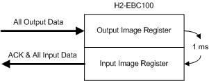
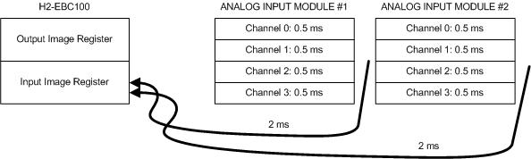
Time(4) = 2ms x
#ofEBCs
The H2-EBCs and H4-EBCs have an image
registers that their masters (i.e. a PC or an ERM) talk to. It takes
2 ms to read or write data to these registers and get an
acknowledgment back. Even when figuring response time (which is what
we are doing), all the EBCs connected to the master are going to
contribute to delay in getting a change to an output, or reading a
change from an input in the EBC you are interested in simply because
the master has to poll all the slaves in his list. And this takes
time. Thus it takes 2 ms times the number of EBCs in the network
that this particular master is talking to. When considering Discrete
I/O, there is essentially no more delay added to this time.
Time(5) = 2ms x
Total#ofAIChForBase
The H2-EBC and H4-EBCs are
continually updating their image registers with the data from all
analog input (AI) modules. Even though there are 4 data types the
only ones that really have any affect on response time are the
analogs (word in, word out). The maximum time it could take the
EBC to read a new value from an analog input module is 2 ms per
channel. But this delay is increased as more analog input channels
are added to the base. The more analog input channels in the base,
the slower the over all response of all analog input channels in
the base. Please note that this has to do with the total number of
analog input channels, not analog input modules.
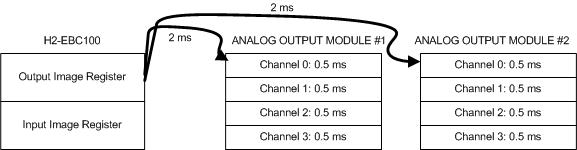
Time(6) = 2ms x
Total#ofAOChForBase
The H2-EBC and H4-EBCs are
continually updating their analog output (AO) modules with the
data from their image registers. Even though there are 4 data
types the only ones that really have any affect on response time
are the analogs (word in, word out). The maximum time it could
take the EBC to write a new value to an analog output module is 2
ms per channel. But this delay is increased as more analog output
channels are added to the base. The more analog output channels in
the base, the slower the over all response of all analog output
channels in the base. Please note that this has to do with the
total number of analog output channels, not
analog output modules.
Time(7) =
Specified for particular module
For AI it is generally called "Data Acquisition Time"
For AO it is generally called "Conversion Setting Time"
The time it takes to see a change from
a particular analog input channel until it actually shows up as data
on the EBC bus is specified as the "Data Acquisition Time"
of that particular module and can be found in its specs. Likewise
the time it takes for the data on the bus to show up as a change in
the output of the analog output channel is called "Conversion
Setting Time" or sometimes just "Conversion Time" and
can be found in its specs.
Time(8) = 1ms +
(1ms x Total#of8ChAOModsForBase) + (1.5ms x
Total#of16ChAOModsForBase)
The T1H-EBC has an image register that
its master (i.e. a PC or an ERM) talks to. It normally takes 1 ms to
read or write data to this register and get an acknowledgment back.
However, unlike the H2-EBC or the H4-EBC it is not fixed. Instead it
is so fast that whereas the H2-EBC and the H4-EBC delays divide up
into a "read/write time" and an "analog in/analog out" time using
formulas (4), (5) and (6) above, the T1H-EBC combines them into one
thing; "read/write & analog). This 1 ms delay is
increased slightly if you have analog outputs installed in the EBC.
What happens is when a write is performed to an analog output in the
EBC, the normal scan is interrupted and the EBC immediately writes
the data to the analog output module. So for each 8-channel analog
output module, you add an additional 1 ms of delay. For each
16-channel analog output module you add 1.5 ms. Reading analog
inputs, however, is so fast it is negligible. Please note that this
has to do with the total number of analog output modules
in the base, not analog output channels (opposite of
H2-EBC and H4-EBC).
Time(9) = 1ms
The T1H-EBC has an image register that
its master (i.e. a PC or an ERM) talks to. It normally takes 1 ms to
read or write data to this register and get an acknowledgment back.
However, unlike the H2-EBC or the H4-EBC it is not fixed. Instead it
is so fast that whereas the H2-EBC and the H4-EBC delays divide up
into a "read/write time" and an "analog in/analog out" time using
formulas (4), (5) and (6) above, the T1H-EBC combines them into one
thing; "read/write & analog." This 1 ms delay is increased
slightly if you have analog outputs installed in the EBC. However,
when reading analog inputs, it is so fast it is negligible, so no
additional time is added to the 1 ms as in formula (8) above.
Time(10) = 1ms x
#ofH2EBC100s
Like the H2-EBCs and H4-EBCs, the
H2-EBC100s have an image registers that their masters (i.e. a PC or
an ERM) talk to. Because of the faster processor in the H2-EBC100 it
only takes 1ms to read or write data to these registers and get an
acknowledgment back. (i.e. the decrease in read/write time is not
significantly improved by the 100Mbps VS the 10Mbps, but rather the
faster processor in the H2-EBC100 itself). Even when figuring
response time (which is what we are doing), all the H2-EBC100s
connected to the master are going to contribute to delay in getting
a change to an output, or reading a change from an input in the
H2-EBC100 you are interested in simply because the master has to
poll all the slaves in his list. And this takes time. Thus it takes
1 ms times the number of H2-EBC100s in the network that this
particular master is talking to. When considering Discrete I/O,
there is essentially no more delay added to this time.

Time(11) = 2ms +
(0.5ms x #ofAIChsOfMod)
Like the H2-EBCs and H4-EBCs the
H2-EBC100s are continually updating their image registers with the
data from all analog input (AI) modules. Even though there are 4
data types the only ones that really have any affect on response
time are the analogs (word in, word out). The maximum time it could
take the H2-EBC100 to read a new value from an analog input module
is 0.5 ms times the number of channels that particular analog input
module has enabled plus an inherent delay of 2 ms for the module
itself. Unlike the H2-EBC and H4-EBC analog input reads, this delay
is not increased as more analog input channels are
added to the base. In other words if more analog input channels are
added to the base, this will not affect the over all
response of any other analog input channels in the base. This
essentially means that the newer H2-EBC100 is running each analog
input module in its base in parallel with the others! Great
feature, eh?
Time(12) = 2ms +
(0.5ms x #ofAOChsOfMod)
Like the H2-EBCs and H4-EBCs the
H2-EBC100s are continually updating their analog output (AO) modules
with the data from their image registers. Even though there are 4
data types the only ones that really have any affect on response
time are the analogs (word in, word out). The maximum time it could
take the H2-EBC100 to write a new value to an analog output module
is 0.5 ms times the number of channels that particular analog output
module has enabled plus an inherent delay of 2 ms for the module
itself. Unlike the H2-EBC and H4-EBC analog output writes, this
delay is not increased as more analog output
channels are added to the base. In other words if more analog output
channels are added to the base, this will not
affect the over all response of any other analog output channels in
the base. This essentially means that the newer H2-EBC100 is running
each analog output module in its base in parallel with the
others! Great feature, eh?
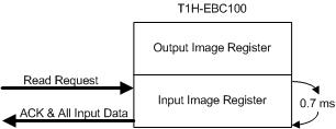
Time(13) = 0.7ms
Like the T1H-EBC the T1H-EBC100 has an
image register that its master (i.e. a PC or an ERM) talks to. It
normally takes 0.7 ms to read or write data to this register and get
an acknowledgment back. However, unlike the H2-EBC or the H4-EBC it
is not fixed. Instead it is so fast that whereas the H2-EBC and the
H4-EBC delays divide up into a "read/write time" and an "analog
in/analog out" time using formulas (4), (5) and (6) above, the
T1H-EBC100 combines them into one thing; "read/write & analog."
This 0.7 ms delay is increased slightly if you have analog outputs
installed in the EBC. However, when reading analog inputs, it is so
fast it is negligible, so no additional time is added to the 0.7 ms
as in formula (8) above.
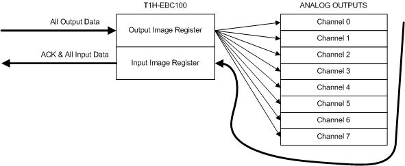
Time(14) = 0.7ms +
(0.7ms x Total#of8ChAOModsForBase) + (1ms x
Total#of16ChAOModsForBase)
Like the T1H-EBC the T1H-EBC100 has an
image register that its master (i.e. a PC or an ERM) talks to. It
normally takes 0.7 ms to read or write data to this register and get
an acknowledgment back. However, unlike the H2-EBC or the H4-EBC it
is not fixed. Instead it is so fast that whereas the H2-EBC and the
H4-EBC delays divide up into a "read/write time" and an "analog
in/analog out" time using formulas (4), (5) and (6) above, the
T1H-EBC100 combines them into one thing; "read/write & analog."
This 0.7 ms delay is increased slightly if you have analog outputs
installed in the T1H-EBC100. What happens is when a write is
performed to an analog output in the T1H-EBC100, the normal scan is
interrupted and the T1H-EBC100 immediately writes the data to the
analog output module. So for each 8-channel analog output module,
you add an additional 0.7 ms of delay. For each 16-channel analog
output module you add 1 ms. Reading analog inputs, however, is so
fast it is negligible. Please note that this has to do with the
total number of analog output modules in the base,
not analog output channels (opposite of H2-EBC and
H4-EBC).
A Final Word
With the above 14 formulas you can
calculate worse-case response times for as many pieces in your
particular application as you desire. Of course statistics teach us that
the typical time will generally be about half of worse case.
THREE EXAMPLES
(1) Using H2-ERM and H2-EBC
Lets say we have a PLC with a scan
time of 20 ms, an H2-ERM, two H2-EBCs and the EBC we are interested
in has one 8-channel analog output (F2-08DA-2), and one 8-channel
analog input (F2-08AD-1). The network is isolated.
First let's calculate the response
time from the PLC to a signal change on the analog output module.
According to the above chart I would use FORMULAs 2, 3, 4, 6 &
7, thus:
Time(2)
= PLCScanTime x 4 (or 3)
= 20 x 4 = 80 ms (multiply by 4 because we have
all 4 data types in the EBC base)
Time(3) = Microseconds
= 0 ms (this is negligible)
Time(4) = 2ms x #ofEBCs
= 2 x 2 = 4 ms (two EBCs on the network)
Time(6) = 2ms x
Total#ofAOChForBase = 2 x 8 = 16
ms
Time(7) = "Conversion Setting
Time" for AO = 9 ms (as
specified for the F2-08DA-2)
Thus the response time from PLC to
signal change on analog output = 80 + 0 + 4 + 16 + 9 = 109
ms (worse case)
Next let's calculate the response
time from a change on the analog input signal to the PLC data.
According to the above chart I would use FORMULAs 2, 3, 4, 5 &
7, thus:
Time(2)
= PLCScanTime x 4 (or 3)
= 20 x 4 = 80 ms (same as above)
Time(3) = Microseconds = 0 ms
(same as above)
Time(4) = 2ms x #ofEBCs = 2 x 2 = 4
ms (same as above)
Time(5) = 2ms x Total#ofAIChForBase = 2 x
8 = 16 ms
Time(7) = "Data Acquisition Time" for AI
= 3 ms/channel = 3 x 8 = 24 ms (as specified
for the F2-08AD-1)
Thus the response time from signal
change on analog input to PLC = 80 + 0 + 4 + 16 + 24 = 124
ms (worse case)
(2) Using H2-ERM and H2-EBC100
Lets try the same thing as above, only
instead of H2-EBCs we replace them with H2-EBC100s.
First let's calculate the response
time from the PLC to a signal change on the analog output module.
According to the above chart I would use FORMULAs 2, 3, 7, 10
& 12 thus:
Time(2)
= PLCScanTime x 4 (or 3)
= 20 x 4 = 80 ms (multiply by 4 because we have
all 4 data types in the EBC base)
Time(3) = Microseconds
= 0 ms (this is negligible)
Time(7) = "Conversion Setting
Time" for AO = 9 ms (as
specified for the F2-08DA-2)
Time(10) = 1ms x #ofH2EBC100s
= 1 x 2 = 2 ms (two EBC100s on the network)
Time(12) = 2ms + (0.5ms x #ofAOChsOfMod)
= 2 + (0.5 x 8) = 2 + 4 = 6 ms
Thus the response time from PLC to
signal change on analog output = 80 + 0 + 9 + 2 + 6 = 97
ms (worse case)
Next let's calculate the response
time from a change on the analog input signal to the PLC data.
According to the above chart I would use FORMULAs 2, 3, 7, 10
& 11 thus:
Time(2)
= PLCScanTime x 4 (or 3)
= 20 x 4 = 80 ms (same as above)
Time(3) = Microseconds = 0 ms
(same as above)
Time(7) = "Data Acquisition Time" for AI
= 3 ms/channel = 3 x 8 = 24 ms (as specified
for the F2-08AD-1)
Time(10) = 1ms x #ofH2EBC100s
= 1 x 2 = 2 ms (same as above)
Time(11) = 2ms + (0.5ms x #ofAIChsOfMod)
= 2 + (0.5 x 8) = 2 + 4 = 6 ms
Thus the response time from signal
change on analog input to PLC = 80 + 0 + 24 + 2 + 6 = 112
ms (worse case)
So you can see that replacing the
H2-EBC with the H2-EBC100 improved the response time in both
directions.
(3) Using H2-ERM and T1H-EBC
Lets say we have a PLC with a scan
time of 20 ms, an H2-ERM, a T1H-EBC which has one 8-channel analog
output (T1F-08DA-2), and two 8-channel analog inputs (T1F-08AD-1).
The network is isolated.
First let's calculate the response
time from the PLC to a signal change on the analog output module.
According to the above chart I would use FORMULAs 2, 3, 7 & 8
thus:
Time(2)
= PLCScanTime x 4 (or 3)
= 20 x 4 = 80 ms (multiply by 4 because we have
all 4 data types in the EBC base)
Time(3) = Microseconds
= 0 ms (this is negligible)
Time(7) = "Conversion Setting
Time" for AO = 0.1 ms (as
specified for the T1F-08DA-2)
Time(8) = 1ms + (1ms x
Total#of8ChAOModsForBase) + (1.5ms x
Total#of16ChAOModsForBase) = 1 + (1 x 1)
+ (1.5 x 0) = 1 + 1 + 0 = 2 ms
Thus the response time from PLC to
signal change on analog output = 80 + 0 + 0.1 + 2 = 82.1
ms (worse case)
Next let's calculate the response
time from a change on the analog input signal to the PLC data.
According to the above chart I would use FORMULAs 2, 3, 7 &
thus:
Time(2)
= PLCScanTime x 4 (or 3)
= 20 x 4 = 80 ms (same as above)
Time(3) = Microseconds = 0 ms
(same as above)
Time(7) = "Data Acquisition Time" for AI
= 5 ms/channel = 5 x 8 = 40 ms (as specified
for the T1F-08AD-1)
Time(9) =
1ms
Thus the response time from signal
change on analog input to PLC = 80 + 0 + 40 + 1 = 121 ms
(worse case)
EBC FAQ0018
27-Feb-2003
Q: Will Wonderware's 205/405 EBC driver work with the T1H-EBC?
A: No. Their original driver will not work with the T1H-EBC. Must
have an updated driver for this to work. Check with Wonderware to see
if they have updated their driver to support T1H-EBC.
EBC FAQ0019
27-Feb-2003
Q: T1H-EBC shows up in NetEdit with a Name and Description as
"???EBC" but in ERM Workbench it is "Term EBC."
A: The default Name and Description for the T1H-EBC is "???EBC,"
but this can be changed with NetEdit.
EBC FAQ0020
26-Feb-2003
Q: Need to update the booter/firmware for EBC. Where can I obtain
the latest booter/firmware files?
A: This is done automatically using the Live Update feature of
NetEdit3.
- You must have an Internet connection.
- Download NetEdit3 and install (Support
--> Utilities; scroll down to NetEdit3 section); download the .ZIP
file and install.
- Execute NetEdit3.
- In NetEdit3: File --> Live
Update; then press the <GO> button.
The latest booter/firmware files (.BIN)
are then loaded onto your PC in the HAPTools\Images folders. Now you can
use NetEdit3 to update your booter/firmware.
- Connect your PC to the EBC's
network and press <Scan Network> button in NetEdit3.
- Right-click on your EBC and select
"Update booter..." or "Update firmware"
EBC FAQ0021
28-Feb-2003
Q: Can I use Wonderware's InControl software to control a
DirectLogic rack of I/O?
A: Yes. Wonderware makes a driver that will talk directly to our
H2-EBC and H4-EBC. You will have to go to the Wonderware website and
search for it (http://www.wonderware.com)
or call them and order it.
EBC FAQ0022 (see also
ERM FAQ0012)
06-Mar-2003
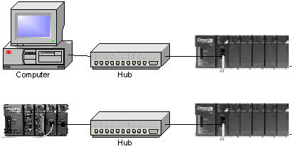
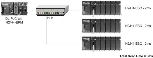
Q: Is there any advantage of using a switch over a hub with
ERM/EBC network?
A: Since the ERM/EBC network is supposed to be dedicated, then
the answer is "no."
However, if the ERM/EBC are on a network
that has other devices (not advisable!) then of course, one may prove to
be more advantageous given the scenario. A hub blindly repeats data that
it hears on one port to all of its ports. Therefore only one Ethernet
node connected to it can talk at a time. A switch, however, evaluates
the source and destination of the Ethernet packet and can therefore
learn paths. This allows many Ethernet nodes to talk to one another over
private connections simultaneously through the switch. A switch would
probably work out better if the ERM/EBC are on a regular office PC
network (again, not advisable!)
EBC FAQ0023 (see also
ERM FAQ0014; ECOM FAQ0019; EDRIVE FAQ0005; EZ Ethernet FAQ0014)
26-Mar-2003
Q: For my Ethernet network that would exceed 100 meters, is a
standard hub considered a repeater so as to increase the permissible
length?
A: Yes. The maximum distance per 10BaseT cable segment is 100
meters. Repeaters (e.g. hubs, bridges, etc.) extend the distance. Each
cable segment attached to a repeater can be 100 meters. Thus, two
repeaters can gain you a total of 300 meters distance.
EBC FAQ0024 (see also
ERM FAQ0017; WinPLC FAQ0005)
22-Apr-2003
Q: How many EBCs can one ERM support?
A: Normally 16. But if the CPU is a Think&Do WinPLC then this
is limited to 1 (this limitation does not apply to the WinCE-only
version of the WinPLC).
EBC FAQ0025
10-Sep-2002
Q: When using H4-EBC base configuration, what is the difference
between F4-08THM vs F4-08THM Unipolar?
A: Normally the F4-08THM is used with bipolar thermocouples and
returns a 2's compliment value temperature in the range of -32768 to
+32767. However, if unipolar thermocouples are used with the F4-08THM
module and it is set up as such, then it returns a temperature in the
range of 0 to 65535. So, it is necessary for the EBC to know this so
that it will know when and when not to convert the value to 2's
compliment.
EBC FAQ0026
13-Sep-2002
Q: When attempting to update the firmware for an T1H-EBC, the LINK
GOOD and ERROR lights come on.
A: If no lights come on before seeing the LINK GOOD and then the
ERROR light comes on, then it could be a hardware problem (return for
repair) or it could be that the firmware is
corrupt.<INCOMPLETE><INCOMPLETE>
EBC FAQ0027
13-Sep-2002
Q: When attempting to update the firmware for an T1H-EBC, the
ERROR lights flashes.
A: If the ERROR light is flashing this could indicate an error
code by the number of times it flashes before a pause:
| BLINKS |
MEANING |
REMEDY |
| Rapid
blinking |
Operating
System (OS) OK, modules removed |
Check
modules |
| 2 |
No
Operating System (OS) found |
Load
firmware |
| 3 |
Ethernet
initialization problem |
If
problem is persistent over power cycling, send in for repair |
| 4 |
Invalid
boot version |
Upgrade
booter to match what firmware requires |
EBC FAQ0028 (see also
SERIO FAQ0001; WinPLC FAQ0012)
09-Sep-2002
Q: Are there slot restrictions for the SERIO module?
A: There is no slot restriction for the H2-SERIO module.
EBC FAQ0029 (see also CTRIO FAQ0034; ERM
FAQ0019)
18-Nov-2015
Q: Will the CTRIO/CTRIO2 work in the local expansion bases of
DL205 or DL405 line?
A: No. Do not install the H4-CTRIO nor the H2-CTRIO/CTRIO2 in
local expansion. It will however work in the ERM/EBC configuration. So
you can expand the I/O using the ERM/EBC instead.
EBC FAQ0030 (see also WinPLC FAQ0013, CTRIO
FAQ0014)
17-Nov-2015
Q: What is the expected hit on the scan time for adding an
H2-CTRIO/CTRIO2 to WinPLC or EBC/EBC100 rack? When connected with
Entivity and adding more than one H2-CTRIO/CTRIO2 I get a timeout.
A: This is different for each product:
For WinPLC, there could be a detectable
hit (however, small) simply because it has a comparatively slower
processor (100MHz).
On the EBC/EBC100 itself, the addition of
a CTRIO will probably not be noticeable at all simply because the
EBC/EBC100 has only one thing to do . . . update its I/O.
On a Think&Do or Entivity application
there will be about 7ms per CTRIO/CTRIO2 hit due to the number of tags
that are created to handle the extra I/O scanning of the CTRIO/CTRIO2
from the PC. Thus, in the Connectivity Center of this software, under
"Attributes" you must increase the "Timeout Value for Retries(ms)" value
accordingly.

EBC FAQ0031
19-Sep-2002
Q: After attempting to upgrade the booter now my T1H-EBC will not
work at all.
A: The booter is definitely critical when it is being updated. In
older versions if it was corrupted during the update, there was no way
to recover and the EBC would just have to be sent back to Host
Engineering to be fixed! With the latest booter (at least v3.0.102)
you can now recover from this fatal state if trying to update later
versions. However, if your EBC will now no longer function (won't
accept booter nor firmware) then it must be shipped to Host
Engineering for repair. The latest booter is always included in the
firmware download ZIP file on our website.
EBC FAQ0032
19-Sep-2002
Q: Unable to see any of the THM, RTD or 08AD-1 modules in H2-EBC,
H4-EBC and T1H-EBCs.
A: This is due to the THM, RTD and 08AD-1 modules powering up with
the broken-transmitter bits turned on (before they are actually
checked). We compensated the problem in our latest firmware for all
EBCs. Must have at least EBC firmware v2.1.296.
EBC FAQ0033 (see also
ECOM 0028; ERM FAQ0020, EDRV FAQ0007, EZ Ethernet FAQ0017; DirectSOFT
FAQ0181; DS Data FAQ0088; SDK FAQ0012; NetEdit FAQ0013)
20-Jul-2018
Q: What Ethernet protocols are used by your products?
A: Refer to chart below:
|
Product |
Ethernet Protocols |
| UDP/IP |
IPX |
TCP/IP |
Raw Ethernet Broadcast (1) |
| K-seq |
DirectNet |
ECOM (2) |
Koyo Backplane |
User Defined Data |
Proprietary (1) |
K-seq |
DirectNet |
ECOM (2) |
Proprietary (1) |
Modbus TCP Master |
Modbus TCP Slave |
Proprietary (1) |
Koyo Backplane |
| Hardware |
ECOM |
Y |
Y |
Y |
Y (3) |
Y (4) |
|
Y |
Y |
Y |
|
|
|
|
Y (5) |
| ECOM100 |
Y |
Y |
Y |
Y (3) |
Y (4) |
|
Y |
Y |
Y |
|
Y
(6) |
Y |
|
Y (5) |
| EBC |
|
|
|
|
|
Y |
|
|
|
Y |
|
|
|
|
| EBC100 |
|
|
|
|
|
Y |
|
|
|
Y |
|
Y |
|
|
| ERM |
|
|
|
|
|
Y (7) |
|
|
|
Y (7) |
(8) |
|
|
|
| EDRV |
|
|
|
|
|
Y |
|
|
|
Y |
|
Y (12) |
|
|
| EZ Ethernet |
Y |
Y |
Y |
|
|
|
Y |
Y |
Y |
|
|
|
|
|
| EZ EtherPLUS |
Y |
Y |
Y |
|
|
|
Y |
Y |
Y |
|
Y |
|
|
|
| WinPLC |
|
|
|
|
|
|
|
|
|
|
|
|
Y |
|
| Software |
DirectSOFT |
Y |
Y |
Y |
|
|
|
Y |
Y |
Y |
|
|
|
|
|
| DS Data |
Y |
Y |
Y |
|
|
|
Y |
Y |
Y |
|
|
|
|
|
| Ethernet SDK |
Y (9) |
Y |
|
|
|
Y |
Y (9) |
Y |
|
Y |
|
|
|
|
| NetEdit |
Y (10) |
|
|
|
|
Y (11) |
Y (10) |
|
|
Y (11) |
|
|
|
|
(1)
Not an industry standard. However, protocol is available for 3rd-party
development upon request.
(2) Not really a distinct protocol. This setting is used
to intelligently pick K-sequence or DirectNet as needed by the
hardware/software.
(3) Used when doing ECOM-to-ECOM via RX/WX instructions
with RX/WX Node Map configured in sending ECOM.
(4) Used when doing ECOM-to-PC (Report-by-Exception) via
RX/WX instructions (Address 90 only) with ECOM's dipswitch 7 set ON.
(5) Used when doing ECOM-to-ECOM via RX/WX instructions
without RX/WX Node Map configured in sending ECOM.
(6) RX/WX Node Map must be configured in ECOM.
(7) ERM can talk to one slave with UDP/IP and another
with IPX simultaneously.
(8) No longer in planning (i.e.
canceled).
(9) Requires K-sequence protocol spec (request from
Automation Direct)
(10) Uses K-sequence to perform "Test CPU Access!"
function.
(11) Uses this protocol to perform "Show Base
Contents..." function.
(12) The older HA-EDRV2 cannot talk Modbus TCP.
EBC FAQ0034 (see also
ERM FAQ0021, WinPLC FAQ0014)
05-Feb-2008
Q: After writing configuration to ERM and EBC get "Error 228 -
Backplane error."
A: Error 228 is defined as "Backplane read/write request queue
full" and it means that for some reason the CPU is either rejecting
requests from its ERM or not accepting them. Common causes:
- Bad backplane (local base).
- Bent pins on ERM (if using H4-ERM), or
CPU.
- H2-ERM installed in Slot 0 (slot next
to the DL205 CPU).
- Power budget in the local base is being
exceeded (lack of sufficient power).
- CPU memory scrambled: Try (1) Clear PLC
memory (all); (2) Program END instruction; (3) Put CPU in RUN; (4)
Power-cycle entire system.
EBC FAQ0035
05-Dec-2003
Q: Do you make or recommend any wireless Ethernet devices that
could be used with or actually replace the EBC?
A: No, but if you bought standard wireless Ethernet switches/hubs,
the EBC should work with those. However, you may have to increase the
timeout and retry values due to the wireless configuration.
EBC FAQ0036 (see also
NetEdit FAQ0008)
26-Sep-2002
Q: Using NetEdit to configure an H4-EBC, but the F4-16DA-2 is not
listed as an option to put in the slots.
A: You can choose one of two things:
- Download a later version of NetEdit
from our website.
- Configure it using the F4-16DA-1
instead. It has the same "signature" as the F4-16DA-2 and it will work
just fine.
EBC FAQ0037
27-Sep-2002
Q: The EBC ERR light comes on when Think&Do is in the RUN mode,
but not when it is in the I/O View.
A: This is due to the increase in the scan time in the RUN mode.
The I/O View scan time is much quicker than the RUN mode. Therefore
you must use Think&Do to increase the EBC timeouts and perhaps
even the Retries value as well.
EBC FAQ0038 (see also
CTRIO FAQ0039; PBC FAQ0006)
27-Aug-2002
Q: In order to use the newer T1H-CTRIO or H4-CTRIO, what are the
requirements as far as configuration software, hardware and
firmware?
A: Here are the requirements:
- CTRIO Workbench needs to be at least
v2.1.2.
- T1H-CTRIO firmware needs to be at least
v2.1.2.
- H4-CTRIO firmware needs to be at least
v2.1.2.
- If using T1H-CTRIO in T1H-EBC the
T1H-EBC hardware needs to be at least "2I" and firmware v1.0.444.
- If using T1H-CTRIO in T1H-PBC the
T1H-PBC hardware needs to be at least "2D" and firmware v1.1.10.
- If using H4-CTRIO in H4-EBC the H4-EBC
hardware needs to be at least "4F" and firmware v2.1.328.
- If using H4-CTRIO in D4-450 the D4-450
needs to be at least T1.985.
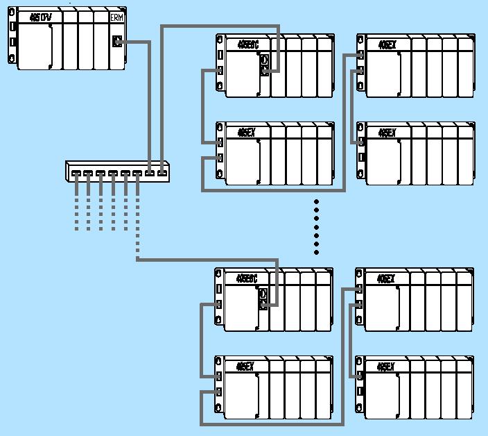
EBC FAQ0039 (see also
ERM FAQ0022)
08-Oct-2002
Q: Using H4-ERM to H4-EBC. Does this configuration support the use
of D4-EX local I/O expansion modules off of the H4-EBC?
A: Yes. The H4-ERM can have up to 16 H4-EBC slaves. On each H4-EBC
it is possible to utilize the D4-EX local I/O expansion to attach 3
more 405 bases. Thus that is 16 x 4 = 64 total 405 bases of I/O
attached to one ERM!
EBC FAQ0040 (see also
ERM FAQ0023)
08-Oct-2002
Q: Using H2-ERM to H2-EBC. Does this configuration support the use
of D2-EM/CM local I/O expansion modules off of the H2-EBC?
A: No. H2-EBC does not support the local I/O expansion of the
DL250-1/260 variety. But the solution is to just use another H2-EBC
instead of using the D2-EM/CM pair.
EBC FAQ0041 (see also
PBC FAQ0007; WinPLC FAQ0015)
09-Oct-2002
Q: Which H2-EBC, H2-PBC and H2-WPLC work in the newer DL205 "-1"
bases?
A: The following states the hardware revision requirements for
using these products in the newer DL205 "-1" bases (the ones that have
the local expansion I/O connector on the right side):
- H2-EBC must be at least 7F (7F and 8F
work).
- H2-PBC must be at least 2D (2D works).
- H2-WPLC1 must be at least 4K (4K, 5K
& 6K work).
- H2-WPLC2 must be at least 4K (4K, 5K
& 6K work).
- H2-WPLC3 must be at least 1K (1K
works).
Find the hardware revision number on a
label on the right side of the PCB (printed circuit board) as shown:
EBC FAQ0042 (see also
ERM FAQ0025; SDK FAQ0006)
07-Oct-2002
Q: My EBC outputs sometimes go OFF intermittently; at the same time
the Error light on the EBC comes on.
A: When the Error light comes ON, this indicates that the watchdog
circuit in the EBC has fired. By default the EBC's watchdog is set to
250ms. This means that if the EBC doesn't get a communication from its
master (e.g. ERM; Entivity; Ethernet SDK app; KEPDirect; etc.) within
250ms then it will fire. When the watchdog fires the outputs in the
EBC base will all be switched OFF for safety purposes. The watchdog
time can be set via the master configuration software (e.g. ERM
Workbench; Entivity; etc.). It can also be disabled. If the watchdog
is disabled then the outputs in the EBC base will simply freeze to
their last state before the watchdog fired.
Thus in the case above where the outputs
appear to go OFF intermittently, this is probably due to the watchdog
time being too small for the application scan time. So either disable
the watchdog totally (NOT RECOMMENDED FOR SAFETY REASONS), or adjust the
time to a higher value.
EBC FAQ0043 (see also
CTRIO FAQ0043; PBC FAQ0008)
11-Oct-2002
Q: How many T1H-CTRIOs can be installed in one base?
A: For T1H-EBC, 13. For T1H-PBC, 2. The limit is data budget.
EBC FAQ0044
14-Oct-2002
Q: Using the local expansion I/O from an H4-EBC. Is there a bit in
the EBC that indicates when the local expansion I/O has been
disconnected?
A: No. Either:
- Use another EBC, or...
- Wire an input high on the expansion
base, and monitor it independently from the PLC.
EBC FAQ0045
21-Oct-2002
Q: How many modules can be installed in the T1H-EBC?
A: The limit is 16 modules (digital and/or analog). However, in
the past we have found that there are certain apparently random
combinations of 16 modules that do not function properly. When this
occurs usually the T1H-EBC is unable to see the module(s) at the end
of the configuration. So far we have not been able to nail down
exactly the rhyme or reason behind such failures but we are sure it
has to do with backplane impedance. Fortunately this is a very rare
thing. If this happens with your configuration, try a few of the
following suggestions:
- Change the order of the modules.
- Install in-line power supplies as
necessary for power budget.
- Uninstall in-line power supplies if
they are not needed.
- Uninstall local I/O expansion cables if
possible and put all modules in a straight line.
EBC FAQ0046 (see also
ERM FAQ0029)
25-Oct-2002
Q: Can an EBC support an ERM in its base?
A: No. The only things that can support ERMs are a regular DL PLC
or a WinPLC.
EBC FAQ0047 (see also Do-more
FAQ0038; CTRIO FAQ0046; ECOM FAQ0036; EDRV FAQ0009; ERM FAQ0030;
EZ Ethernet FAQ0018; PBC FAQ0009; PSCM FAQ0001; WinPLC FAQ0018;
NetEdit FAQ0014; MB-GATEWAY FAQ0003)
13-Dec-2017
Q: What software tool do I use to upgrade/downgrade my Host
Engineering hardware?
A: Refer to the following:
| Host Hardware |
Part Number |
Firmware/Booter Upgrade Tool |
CTRIO
CTRIO2
|
H0-CTRIO
H4-CTRIO
H0-CTRIO2
|
CTRIO
Workbench
|
|
H2-CTRIO
T1H-CTRIO
H2-CTRIO2
T1H-CTRIO2
|
CTRIO
Workbench or
Do-more Designer
|
DM1
DM1E |
BX-DM1-x
BX-DM1E-x
H2-DM1
H2-DM1E
T1H-DM1
T1H-DM1E
|
Do-more
Designer |
EBC
EBC100 |
H2-EBC
H4-EBC
T1H-EBC
T1H-EBC100
H2-EBC100
|
NetEdit3 |
ECOM
ECOM100 |
H0-ECOM
H2-ECOM
H4-ECOM
H0-ECOM100
H2-ECOM100
|
ECOMLT (POM)
|
BX-P-ECOMLT |
EDRV
EDRV100
|
GS-EDRV
GS-EDRV100
|
ERM
ERM100
|
H2-ERM
H4-ERM
H2-ERM100
|
NetEdit3
or
ERM Workbench |
| EZ Ethernet |
EZ
Ethernet
EZ EtherPLUS |
EZ Touch |
| MB-GATEWAY |
MB-GATEWAY |
NetEdit3 |
| PBC |
H2-PBC |
| PSCM |
H0-PSCM
H2-PSCM
|
| WinPLC |
WinPLC |
WinPLC
Workbench |
NOTE:
All the firmware for the above products can be downloaded using
NetEdit3's File --> Live Update... The firmware files are
stored in c:\HAPTools\Images folder, or in the case of the Do-more
PLCs, under the Images subfolder in the Do-more Designer's
installation Bin folder.
EBC FAQ0048 (see also CTRIO FAQ0013; ERM
FAQ0031; WinPLC FAQ0029; SDK FAQ0013)
17-Nov-2015
Q: Is it possible to utilize the CTRIO System Functions everywhere
the CTRIO/CTRIO2 can be installed?
A: In firmware v2.x System Functions were added to the CTRIO
products (H0-, H2-, H4- and T1H-CTRIO) and are present in all CTRIO2
modules. These System Functions allow the writing (and reading) of
various internal registers of the CTRIO/CTRIO2. The following table
shows what scenarios that these System Functions can be used and how to
use them:
|
System Functions |
CTRIO/CTRIO2 Installation
|
| Do-more Local Base |
Do-more Ethernet I/O Base with EBC100
|
DL PLC Local Base |
DL PLC Local Expansion Base |
DL PLC with ERM-EBC |
WinPLC (Think&Do) Local Base |
WinPLC (Think&Do) with ERM-EBC
|
Think&Do (Entivity) to EBC |
Ethernet SDK to EBC |
|
|
| Mapped System Functions |
Status of Inputs |
YES (1)
|
YES (1)
|
YES (3)
|
NO (5)
|
YES (3)
|
YES (7)
|
YES (7) |
YES (7)
|
YES (9)
|
| Mode & Status of Outputs |
YES (1)
|
YES (1)
|
YES (3)
|
NO (5)
|
YES (3)
|
YES (7)
|
YES (7)
|
YES (7)
|
YES (9)
|
|
| CTRIO/CTRIO2 Shared RAM System Functions |
0x01 - Read all registers |
YES (2)
|
YES (2)
|
YES (4)
|
NO (5)
|
NO
(6)
|
YES (8)
|
YES (8)
|
YES (8)
|
YES (10) |
| 0x02 - Write all registers |
YES (2)
|
YES (2)
|
YES (4)
|
NO (5)
|
NO
(6)
|
YES (8)
|
YES (8)
|
YES (8)
|
YES (10) |
|
| 0x03 - Read one register |
YES (2)
|
YES (2)
|
YES (4)
|
NO (5)
|
NO
(6)
|
YES (8)
|
YES (8)
|
YES (8)
|
YES (10) |
|
| 0x04 - Write one register |
YES (2)
|
YES (2)
|
YES (4)
|
NO (5)
|
NO
(6)
|
YES (8)
|
YES (8)
|
YES (8)
|
YES (10) |
|
| 0x05 - Write reset value |
YES (2)
|
YES (2)
|
YES (4)
|
NO (5)
|
NO
(6)
|
YES (8)
|
YES (8)
|
YES (8)
|
YES (10) |
|
(1) - Mapped to the
CTRIO/CTRIO2 device structure members
(2) - Use the CTREGWR & CTREGRD instructions (can
only read/write one register at a time)
(3) - Mapped to V-memory as configured in the
CTRIO/CTRIO2 using CTRIO Workbench
(4) - Use the CTRRGWR & CTRRGRD IBox instructions
(can only read/write one register at a time)
(5) - CTRIO/CTRIO2
will not work in local expansion bases
(6) - No way to tell the ERM/ERM100 to access the
Shared RAM of CTRIO/CTRIO2 in EBC/EBC100 base
(7) - Mapped to memory as configured in Think&Do
(8) - Use Shared RAM Operations for CTRIO/CTRIO2 in a
CALL block
(9) - Mapped as shown with NetEdit3 Show Base Contents
(10) - Use HEIWriteSharedRAM & HEIReadSharedRAM
routines
EBC FAQ0049 (see also
CTRIO FAQ0055)
10-Mar-2003
Q: Are there any slot restrictions for the CTRIO if installed
in an EBC?
A: The following restrictions apply:
- If using H2-EBC with a hardware
revision less than 9A, you can install H2-CTRIO in all slots except
Slot 0 (the one adjacent to the EBC itself).
- If using H2-EBC with a hardware
revision of 9A or greater, there are no slot restrictions.
- If using H4-EBC there are no slot
restrictions.
- If using T1H-EBC there are no slot
restrictions.
EBC FAQ0050 (see also
SDK FAQ0010)
14-Apr-2003
Q: Using the Ethernet SDK's EBCDemo.EXE but getting "????" for
analog module F2-08DA-2 installed in H2-EBC.
A: This is because the EBCDemo.EXE was created before the
F2-08DA-2 module was created; so it doesn't know exactly what it is.
Also make sure you have at least H2-EBC firmware version v2.1.128 to
support this newer analog module.
EBC FAQ0051 (see also
SDK FAQ0008)
03-Dec-2002
Q: Using the T1F-14THM thermocouple module; how do I convert the
returned hexadecimal value into a decimal temperature?
A: The EBC that the T1F-14THM module is plugged into has already
converted it to a temperature in the Visual Basic data type called
"long." But, if you want to convert a hexadecimal to a decimal number
you would use something like:
Val(string)
Where string is a hexadecimal
number like "&H10FA."
EBC FAQ0052 (see also
DS Data FAQ0087; DirectSOFT FAQ0180; NetEdit FAQ0012; ECOM FAQ0040;
EDRV FAQ0010; ERM FAQ0034; EZ Ethernet FAQ0026)
27-Apr-2004
Q: Getting various errors when attempting to use NetEdit to see or
establish a link to a Host Ethernet device.
A: Here are know errors and their suggested solutions:
CAUTION: You may want to consult your
Network Administrator before doing any of the solutions below! He/she
may not want you to change your PC's setup at all!
- (1) "Error 10047" - This is an error from Microsoft Winsock. Formally it is
known as "WSAEAFNOSUPPORT" and is described as, "Address family
not supported by protocol family. An address incompatible with the
requested protocol was used. All sockets are created with an
associated address family (that is, AF_INET for Internet
Protocols) and a generic protocol type (that is, SOCK_STREAM).
This error is returned if an incorrect protocol is explicitly
requested in the socket call, or if an address of the wrong family
is used for a socket, for example, in sendto."
Possible causes:
(1) IPX protocol is not installed for your NIC.
(2) TCP/IP protocol not installed for your NIC.
(see EBC
FAQ0057 for installing protocols)
- (2) "Error 10051" - This is an error from Microsoft Winsock. Formally it is
known as "WSAENETUNREACH" and is described as, "Network is
unreachable. A socket operation was attempted to an unreachable
network. This usually means the local software knows no route to
reach the remote host. Very similar to Error 10065 WSAEHOSTUNREACH
only this is usually related to IPX protocol."
Possible causes:
(1) NIC is disabled.
(2) IPX protocol is not installed for your NIC (see
EBC FAQ0057 for installing protocols).
- (3) "Error 10061" - This is an error from Microsoft Winsock. Formally it is
known as "WSAECONNREFUSED" and is described as, "Connection
refused. No connection could be made because the target computer
actively refused it. This usually results from trying to connect
to a service that is inactive on the foreign host---that is, one
with no server application running."
Possible causes:
(1) You have a firewall software installed and enabled (e.g.
ZoneAlarm).
(a) Uninstall it, or...
(b) Disable it, or...
(c) Poke a hole in it by making
exceptions for the NetEdit3.EXE application or for TCP Port # 0x7070
(28784 decimal).
- (4) "Error 10065" - This is an error from Microsft Winsock. Formally it is
known as "WSAEHOSTUNREACH" and is described as, "No route to
host. A socket operation was attempted to an unreachable host.
Very similar to Error 10051 WSAENETUNREACH only this is usually
related to TCP/IP protocol."
Possible causes:
(1) NIC is disabled.
(2) TCP/IP protocol is not installed for your NIC.
(3) Your NIC and the Host Ethernet device are on different
subnets:
(a) Change your NIC's TCP/IP address
to put it on the same subnet as the Host Ethernet device, or...
(b) Change your Host Ethernet
device's TCP/IP address to put it on the same subnet as the NIC,
or...
(c) Change the subnet mask in your
network configuration settings.
-
(5) "Error reading
configuration values from device."
First of all, there was a bug in
versions of NetEdit previous to v3.1, that when you pressed the
Query Network button this error could pop up. If this is the case
then you just need to download a later copy (at least v3.1) of
NetEdit from our website. If this is not the case then
notoriously, this error is caused by one of the following:
- Is the EBC/ECOM/EDRV/ERM/EZ
Ethernet powered up properly? If not, make sure it is.
- Is the LINK GD (link good) light
on? This indicates that the cabling is good.
- While using NetEdit, does the
ACTIVE light blink when changing protocols from IPX to UDP/IP?
This indicates that the EBC/ECOM/EDRV/ERM/EZ Ethernet is
seeing Ethernet packets.
- Is the IPX protocol loaded for the
NIC you are using and enabled? (see EBC
FAQ0057 for installing protocols). There are fewer things to
mess up with IPX, so it is the better protocol to use when trying
to diagnose the problem.
- Is there just one NIC in the PC? If
not, then it is possible that the packets are going out one or
both NICs but being received by the “wrong” NIC as seen from
NetEdit.
- Is there just one LAN connection
loaded for the NIC? Multiple LAN connections (e.g. WAN network
driver) can cause similar problems as with two NICs.
- Is the Network Number for the IPX
protocol set to 00000000? If not, it must be, or it will not talk.
- Is the NIC running at 10Mpbs?
(disconnect NIC cable; reboot PC; reconnect NIC cable). If it is
trying to run at 100Mbps, it will not talk.
- Do you have "802.1p QoS packet
tagging" enabled? If so, disable it (Device Manager, Network
Adapter, Properties, Advanced). This adds information to the IPX
and TCP/IP packets that is not understood by NetEdit.
- Is there firewall software loaded
(e.g. ZoneAlarm)? This can interfere with the IPX and the TCP/IP
protocol packets. We have to disable this software to get ours to
talk properly.
- Is the network hardware verified?
(cabling / hub / EBC/ECOM/EDRV/ERM/EZ Ethernet / NIC)?
If none of these things fix the
problem, then it is possible that the EBC/ECOM/EDRV/ERM/EZ Ethernet
device is defective and you may need to send it in for repair.
- (6) Nothing shows up in the
list, or not all devices show up in the list, or list shows
incomplete data.
NetEdit sends out a broadcast and waits
600 ms for devices to respond. If the devices take longer than this
to respond they will be missing from the list. After the responses
are gathered, NetEdit makes a list and then polls each device in the
list to get detailed data, but waits only 250ms for response from
each device. If the device takes longer than this to respond some of
its data may be missing. This is not a problem on a normal wired
network, but can be a problem on a wireless network where responses
can inadvertently be long and inconsistent. Also, since a broadcast
is used if the devices are on the other side of a LAN or WAN, these
network devices by default will usually block broadcast packets.
However, this does not necessarily mean that you cannot ping the
devices (TCP/IP protocol) and/or use DirectSOFT to link to them
(e.g. by manually entering the IP address). In general, however,
problems like this can also be caused by the things listed in bullet
(5) above.
- (7) The "C" column indicates
an asterisk (*), but there are no conflicts with addresses on the
network.
An asterisk in the "C" column means
NetEdit "sees" an address conflict on the network. First, make sure
that no IP addresses are the same between the devices that NetEdit
sees on the network and the devices NetEdit doesn't see on the
network (i.e. PCs, servers, etc.). Second, make sure none of the IDs
of any of the devices in NetEdit are the same. If there are no
conflicts, this could be caused by an older version of NetEdit.
Therefore make sure you have at least NetEdit3 v3.6c or later.
EBC FAQ0053 (see also
ERM FAQ0035)
14-Oct-2003
Q: When trying to download configuration from ERM Workbench to the
ERM get, "Error trying to reset ERM for download."
A: This is really nothing more than a timeout error and is more
than likely due to one of the following issues:
- Check your network connections and
disable all but the one you are using.
- Disable all NICs except the one you are
using.
- In ERM Workbench, press the <Select
Slaves> button and change the "PC Network Slaves on:" protocol from
IPX to UDP/IP or vise versa.
EBC FAQ0054 (see also
CTRIO FAQ0062; NetEdit FAQ0015)
02-Feb-2005
Q: Using an EBC100 and Modbus TCP protocol, how can I figure out
where the CTRIO parameters are mapped into the Modbus addresses?
A: The easiest way to do this is to use NetEdit3 and CTRIO
Workbench in combination. Follow these steps:
- Using NetEdit3 (at least v3.4) to view
the network that the EBC100 is connected to.
- Right-click on the EBC100 and pick
"Show Base Contents..."
- Scroll down until you see your CTRIO
I/O listed. It will look something like this:
Base 0 : Slot 8 - Module Type 38 - T1H-CTRIO
96
- Bit
inputs
(Modbus
584/984 - Inputs 10025-10120)
96 - Bit
outputs
(Modbus 584/984 - Coils 25-120)
12 - Word
outputs
(Modbus 584/984 - Holding registers 40017-40028)
8 - Double word inputs (Modbus
584/984 - Input registers 30049-30064)
4 - Double word outputs (Modbus 584/984 -
Holding registers 40029-40036)
Here you can see that NetEdit3 has
provided the Modbus addressing for you. Next you need only to see how
these work in the CTRIO.
- Using CTRIO Workbench (at least v2.1.9)
connect to your CTRIO via the EBC100.
- Press the <I/O Map...> button.
(This is assuming that you have already configured your CTRIO the way
you want).
- Select "EBC - Mapped to MODBUS/TCP."
- For "Starting input reg for word
inputs:" enter the "Input register" number that you saw in NetEdit3
(e.g. 30049 in above example).
- For "Starting input for bit inputs:"
enter the "Inputs" number that you saw in NetEdit3 (e.g. 10025 in
above example).
- For "Starting holding reg for word
outputs:" enter the smallest "Holding registers" address that you saw
in NetEdit3 (e.g. 40017; not 40029 in above
example).
- For "Starting coil for bit outputs:"
enter the "Coils" number that you saw in NetEdit3 (e.g. 25 in above
example).
After manually entering these numbers from
NetEdit3 into CTRIO Workbench's I/O mapping screen you can now see all
the parameters and their appropriate Modbus TCP addressing.
EBC FAQ0055 (see also
ERM FAQ0036)
08-May-2002
Q: Analog reads on EBC can sometimes jump by +256.
A: This is due to a timing issue with newer 16AD modules and EBC
PLD chip. If this occurs return EBC to Host for modification.
EBC FAQ0056
07-Mar-2005
Q: What is the Node Address used for?
A: The Node Address of the EBC is just a text field stored in the
EBC.
- If the dipswitches are set to zero
(all off), then the Node Address can be changed using NetEdit or
Ethernet SDK.
- If the dipswitches are set to a non-zero value, then this non-zero
value becomes the Node Address and it cannot be changed via software.
The Node Address was mainly created for
Think&Do/Entivity software users. These software packages just use
IPX protocol to talk to the EBC and therefore must know the EBC's MAC
address. But by having dipswitches on the EBC this allows the
Think&Do/Entivity user to buy an EBC, unpack it, set the Node
Address via the dipswitches, hook it up and then write his application
around the Node Address without having to know the rather cryptic MAC
address of the EBC. Basically, behind the scenes Think&Do/Entivity
software just sends a directed broadcast in IPX and finds the EBC, then
reads its Node Address text field. It then reads the MAC address and
associates this MAC address with the Node Address. This way the customer
doesn't have to configure or even know the MAC address of the EBC. Also,
if the EBC goes bad, he can simply replace this EBC with a new one that
has the same dipswitch setting and he doesn't have to change his
application to adjust for the new MAC address.
Thus for applications other than
Think&Do/Entivity, the Node Address has no specific meaning.
EBC FAQ0057 (see also
DirectSOFT FAQ0183; DS Data FAQ0093; ECOM FAQ0043; EDRIVE FAQ0012; ERM
FAQ0037; EZ Ethernet FAQ0027; NetEdit FAQ0017)
27-Sep-2010
Q: How can I install IPX protocol for my NIC?
A: You can find instructions on how to do this for your
particular operating system by going to Start --> Help &
Support and searching for "Install NWLink." Below are the instructions
from Microsoft for doing this on a WinXP PC. The instructions are
similar for other operating systems (e.g. WinNT, Win98, WinME, Win2K).
To install NWLink IPX/SPX/NetBIOS
Compatible Transport Protocol
(1) Open Network Connections:
(a) Click Start
--> Settings --> Control Panel.
(b) Double-click Network
Connections.
NOTE: You must be a
member of the Administrators group to install protocols. Also, when
IPX is installed it is installed for all your connections. If you
don't want it installed for a certain connection, then right-click
that connection, click Properties and, on either the General
or Networking tab, clear the NWLink IPX/SPX/NetBIOS
Compatible Transport Protocol check box.
(2) Right-click a local area connection, then click Properties.
(3) On the General tab, click Install.
(4) In the Select Network Component Type dialog box,
click Protocol, and then click Add.
(5) In the Select Network Protocol dialog box, click NWLink
IPX/SPX/NetBIOS Compatible Transport Protocol, and then click OK.
IMPORTANT: The IPX/SPX protocol is not available on
WinXP 64-Bit Edition, WinVista or Win7.
EBC FAQ0058 (see also
ERM FAQ0039)
19-Aug-2005
Q: What is the limitation of I/O for the ERM / EBC configuration?
A: The ERM has a limit of 8K bytes (8192 bytes) of I/O data
from all of its EBCs. Each EBC has a data budget of 1400 bytes of I/O.
In other words you will probably run into other limitations before you
run into these limitations.
EBC FAQ0059 (see also
ECOM FAQ0051; EDRIVE FAQ0013; ERM FAQ0040; EZ Ethernet FAQ0028;
NetEdit FAQ0022)
22-Sep-2005
Q: I inadvertently changed the IP address of my Host Engineering
Ethernet device and now NetEdit cannot find it, nor can I ping it.
How can I get it "back?"
A: It can be changed using IPX protocol:
- If IPX protocol is not installed for
your PC's NIC, then install it (see EBC FAQ0057
above).
- Select IPX protocol in NetEdit3 and
edit the IP address.
EBC FAQ0060 (see also
ERM FAQ0041; EDRIVE FAQ0014)
28-Sep-2005
Q: In ERM Workbench, what do the colors of the slave numbers in the
Slave Status box mean?
A: Colors indicate slave status of a particular slave:
| COLOR |
DESCRIPTION |
| Grey |
Slave not
configured. |
| Green |
Slave configured
and ERM successfully communicating with it. |
| Yellow |
Slave configured
and ERM successfully communicating with it, but the slave has an
error in its I/O. |
| Red |
Slave configured
but ERM cannot communicate with it. |
EBC FAQ0061 (see also
ECOM FAQ0052; EDRIVE FAQ0015; ERM FAQ0042; EZ Ethernet FAQ0029;
HA-TADP FAQ0005; WinPLC FAQ0028)
29-Sep-2005
Q: Do any of your Ethernet devices support the next generation of
Internet (IPv6)?
A: No; nor do we have any plans to implement it at this
time.
EBC FAQ0062 (see also
ERM FAQ0043)
04-Oct-2005
Q: How does the F2-8AD4DA-1 and F2-8AD4DA-2 modules log into the
H2-EBC or H2-EBC100? And how is it configured?
A: This module logs in as 8 words in and 8 words out even
though it is really only an 8 word in and 4 word out module. The extra
4 words out are used to configure the module:
5th Word Out = Input resolution
6th Word Out = Input/Output range (F2-8AD4DA-2 only)
7th Word Out = Track & Hold
8th Word Out = <not used>
For the specific bit configurations of the
above, see the manual for the module.
EBC FAQ0063
08-Nov-2004
Q: Using T1H-EBC100 with Modbus on the serial port; discovered that
the EBC100 is responding to all Modbus node addresses seen on the
wire.
A: This is a bug in the T1H-EBC100 firmware. It is fixed in
at least firmware v4.0.1288 or higher. The Modbus/RTU ID (over the
serial port) is now set to the Module ID of the T1H-EBC100. This
Module ID is set by the DIP switches on the module itself, or via
NetEdit3 software.
EBC FAQ0064
15-Dec-2004
Q: Due to a limitation of a Modbus TCP master, cannot address the
50000+ range in the T1H-EBC100 to configure the analog cards.
A: For this very reason, the T1H-EBC100 mirrors the 50000+ range
to the 410000+ range. This means writing to the Holding Register range
(Function Code 06) of 40000 with an offset of 10000 or greater.
EBC FAQ0065 (see also
ECOM FAQ0053; EDRV FAQ0017)
20-Feb-2009
Q: Using a 3rd-party Modbus TCP master (e.g. Wonderware), when
multiple requests are sent to the ECOM100, EBC100, or EDRV,
sometimes some of the packets timeout.
A: The firmware of these devices were originally set up to do one
transaction at a time. Multiple requests to different TCP port numbers
was not a problem. This problem was fixed in:
H0-ECOM100 firmware version 4.0.52 (or
later)
H2-ECOM100 firmware version 4.0.999 (or later)
H2-EBC100 firmware version 4.0.464 (or later)
T1H-EBC100 firmware version 4.0.1309 (or later)
GS-EDRV firmware version 1.1.267 (or later)
EBC FAQ0066 (see also
CTRIO FAQ0069)
26-Jul-2005
Q: When using H2-CTRIO in H2-EBC100, the Output Active bit for the
CTRIO doesn't come on, however, it works in an H2-EBC.
A: This is a bug caused by the firmware of the H2-EBC100. The
DWORD outputs were not getting written to the CTRIO properly. It is
fixed in:
H2-EBC100 firmware v4.0.457 or higher.
EBC FAQ0067 (see also
ECOM FAQ0054)
30-Sep-2005
Q: Does the EBC100 or the ECOM100 support Allen-Bradley Ethernet/IP
protocol?
A: No. However, both the EBC100 and the ECOM100 support Modbus
TCP. Prosoft Technology makes a Modbus TCP card that plugs into
Allen-Bradley systems that could be used to talk to them.
EBC FAQ0068
14-Oct-2005
Q: Using Modbus TCP Master to a T1H-EBC100, if read requests for
the I/O Module Status data are not on the 20-word boundaries,
erroneous data is returned.
A: This is a bug in the firmware of the T1H-EBC100. It is fixed
in:
T1H-EBC100 firmware v4.0.1309 or higher.
EBC FAQ0069 (see also
ECOM FAQ0055; EDRIVE FAQ0018; ERM FAQ0044; EZ Ethernet FAQ0030;
HA-TADP FAQ0006; WinPLC FAQ0032)
15-Nov-2005
Q: What types of Ethernet framing do your Ethernet products
support?
A: All our Ethernet products (ECOM, ECOM100, EBC, EBC100, EDRV,
ERM, EZ Ethernet, EZ EtherPLUS, HA-TADP and WinPLC) all support the
following types of Ethernet framing:
- IEEE 802.2
- IEEE 802.3
- Ethernet II
- Ethernet SNAP
EBC FAQ0070 (see also
ECOM FAQ0061; EDRIVE FAQ0019; ERM FAQ0045; EZ Ethernet FAQ0031;
HA-TADP FAQ0007; WinPLC FAQ0033)
22-Feb-2005
Q: Are the Host Engineering Ethernet products compliant to AS ISO
15745?
A: No.
EBC FAQ0071 (see also
ERM FAQ0046; SDK FAQ0014)
09-Aug-2005
Q: Why can I not see negative temperatures with my T1F-14THM and
T1F-14RTD modules?
A: This is because of a fundamental design difference between the
THM/RTD modules and all other analog modules in Terminator I/O.
Technically all other analog modules in the Terminator I/O line output
24-bit data onto the Terminator I/O bus. The T1H-EBC/T1H-EBC100 looks
at the 24th bit and then sign extends this bit to the 32nd bit. This
allows 32-bit negative numbers to be viewed from all other analog
modules. However, the T1F-14THM and T1F-14RTD modules only output
16-bit data onto the Terminator I/O bus. Thus when the
T1H-EBC/T1H-EBC100 looks at the 24th bit, it never sees this bit set,
and so the sign extension is always with a cleared bit to the 32nd
bit. Thus all 32-bit negative numbers from this configuration will
always be positive. Some suggested solutions are given below this
diagram:
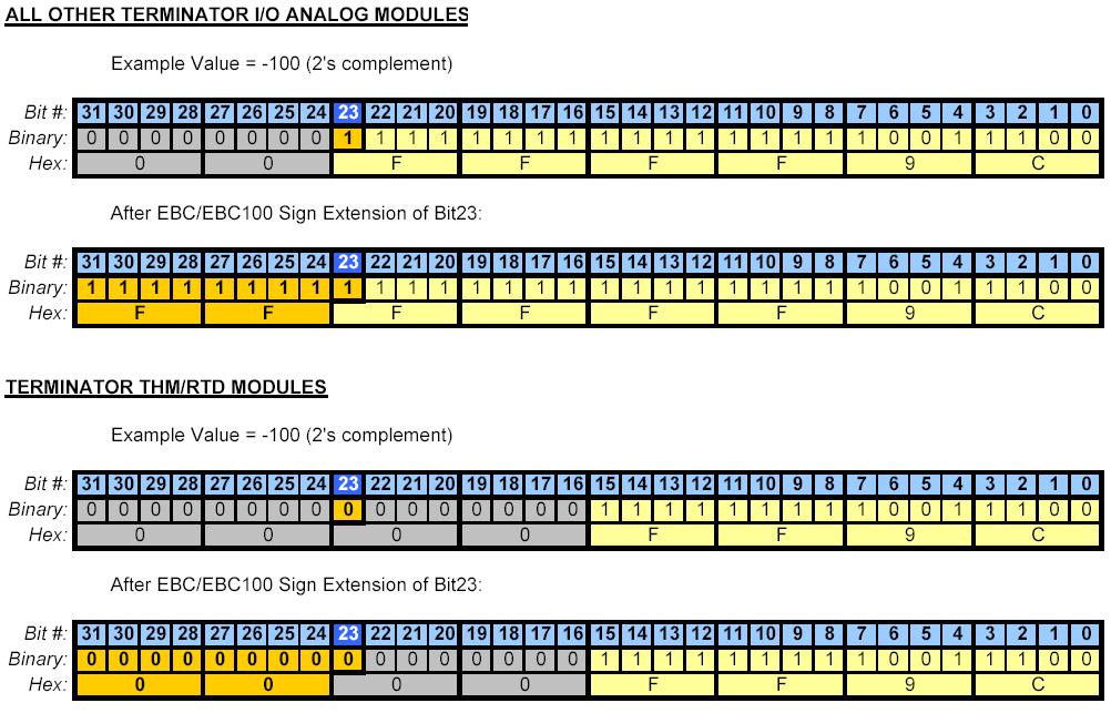
Therefore, whatever is reading the values
of the THM/RTD module from the EBC/EBC100 will have to manipulate the
data in order to make it negative. For example:
- If using Think&Do (Entivity) then
map the 32-bit value to a counter.
- If using Think&Do WinPLC then map
the 32-bit value to a counter.
- If using Ethernet SDK then map the
32-bit value to a 16-bit integer.
- If using a DL PLC --> ERM -->
EBC, then ignore the most significant word.
EBC FAQ0072 (see also
CTRIO FAQ0072; ERM FAQ0047; SDK FAQ0015)
09-Jan-2006
Q: In my H2-ERM/H2-EBC (or H2-EBC100) configuration, the H2-CTRIO
word output (WO) and double-word output (DWO) mapping is different
than where CTRIO Workbench indicates they should be.
A: This is caused by an I/O mapping problem in the H2-EBC and
H2-EBC100 that is fixed in EBC firmware v2.1.441 and later. It has to
do with the H2-CTRIO "I/O type." The H2-CTRIO is now reported as a
Type 7 module instead of a Type 5 module. This new reclassification of
the H2-CTRIO as a Type 7 allows the EBC to manage the order in which
things get mapped.
The symptom shows up as a mapping
discrepancy in the order in which the CTRIO puts the DWOs and the WOs VS
where the ERM Workbench maps them in PLC memory.
For example, for comparison see the chart
below:
| H2-CTRIO Mapping Component |
H2-CTRIO mapping in H2-EBC
(H2-EBC100) with firmware less than v2.1.441 |
H2-CTRIO Mapping in H2-EBC
(H2-EBC100) with firmware v2.1.441 or later |
| 96 Discrete Input (DI) |
X340-477
(V40416-40423) |
X340-447
(V40416-40423) |
| 96 Discrete Output (DO) |
Y320-457
(V40515-40522) |
Y320-457
(V40515-40522) |
| 12 Word Output (WO) |
V2100-2113 |
V2110-2123 |
| 8 Double Word Input (DWI) |
V2000-2017 |
V2000-2017 |
| 4 Double Word Output (DWO) |
V2114-2123 |
V2100-2107 |
NOTE: If you update the
EBC firmware to fix this problem, make sure that you are at least
using CTRIO Workbench v2.1.10 to configure the H2-CTRIO.
EBC FAQ0073
21-Feb-2006
Q: Using T1H-EBC100 and Modbus TCP, I can't write to the
Cofiguration Words (50021-50053) for my T1F-8AD4DA-x combo analog
module.
A: This is a bug in the T1H-EBC100 firmware, and it is fixed in
version 4.0.1313.
EBC FAQ0074
21-Feb-2006
Q: Using T1H-EBC100 and the incorrect I/O shows up in the
addressing (Type 13).
A: This is a hardware bug in the T1H-EBC100 which prevents 16pt
Discrete I/O modules from being logged into the system correctly. The
most common symptom of this problem occurrs if you have a 16pt
Discrete Input module followed by a 16pt Discrete Output module. The
T1H-EBC100 would show both of these modules logged into the same slot
with a module ID of 13.
This bug is fixed in T1H-EBC100 PWB Rev:
6E.
This fix cannot be applied in the field,
you must return the T1H-EBC100 to have the unit serviced. There are two
options available to have the T1H-EBC100 fixed:
1. If you purchased the unit less than 30 days ago, you can return it to
Automationdirect.com through their normal RMA processing system for a
replacement.
2. If you purchased the unit more than 30 days ago, you can contact us
here at Host Engineering via email for instructions on how to ship the
unit directly to us for repair. Send the email inquiry to
support@hosteng.com.
NOTE: This fix is for a very specific hardware related issue. Use the
"Show Base Contents" option in NetEdit v3 to verify that adjacent 16pt
Discrete I/O modules are showing up in the same slot with the Module ID
of 13 before you contact us for a replacement or to have the unit
repaired.
EBC FAQ0075 (see also
NetEdit FAQ0030)
18-Nov-2008
Q: What are the meanings of the Port Mode settings for the
EBC/EBC100 that are seen in Serial Port Settings of NetEdit?
A: The functionality and description of these modes are not
documented anywhere simply because there are no products that fully
utilize them. Basically the EBC has 2 Port Modes (Master/Proxy; K-Seq
Slave) and the EBC100 has an extra 3rd one (Modbus Slave). These modes
are briefly described here:
- Master/Proxy: Entivity (Think&Do), KEPDirect EBC and our
Ethernet SDK actually can utilize this one. In this mode the serial
port is a proxy device. The port is read from and written to via an
Ethernet SDK function (e.g. HEIWriteComm, HEIReadComm). In fact,
when Entivity (Think&Do) and KEPDirect EBC utilize this
functionality, they used our Ethernet SDK to write their code. They
use this functionality to allow their users to connect an HMI device
(like EZTouch) to the EBC/EBC100. In this manner the serial port can
be remotely controlled via a PC over Ethernet. For example:
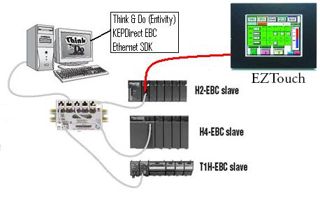
- Modbus Slave: No product currently utilizes this functionality.
This function is only available for the EBC100 because the EBC does
not support Modbus at all. In this mode the serial port acts like a
serial Modbus slave with the Modbus address being the Module ID of
the EBC100. In this mode the EBC100's I/O is mapped for Modbus
addressing. To see where the I/O resides you will have to connect to
the EBC100 via Ethernet and use NetEdit, then right-click on the
EBC100 and choose Show Base Contents:
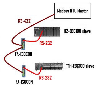
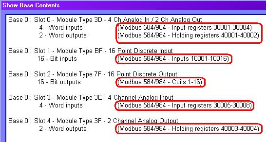
- K-Seq Slave: No product currently utilizes this functionality.
In this mode the serial port emulates the memory of a DL260. In
fact, you can actually make a serial link to it using DirectSOFT! In
this emulation mode, you can read/write to emulated V-memory and
C-bit memory, and also read/write to the I/O of the EBC/EBC100:
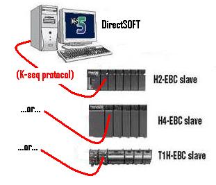
The memory map is as follows:
V0-V7777 - Emulated V-memory (4K words)
V10000-V17777 - EBC/EBC100 Analog Inputs: 512 words = 16 slots x 16
AI x 4 bytes (2 words) each
V20000-V27777 - EBC/EBC100 Analog Outputs: 512 words = 16 slots x 16
AO x 4 bytes (2 words) each
V30000-V37777 - EBC/EBC100 device info
V40400-V40477 - EBC/EBC100 Discrete output memory
V40500-V40577 - EBC/EBC100 Discrete input memory
V40600-V60677 - Emulated C-bit memory
V41200-V41237 - Emulated SP-bit memory
V160000-V163777 - EBC/EBC100 Discrete output memory
V164000-V167777 - EBC/EBC100 Discrete input memory
V170000-V171777 - Emulated C-bit memory (1024 bits)
V177000-V177617 - Emulated SP-bit memory (512 bits)
NOTE: If you
have questions regarding the Modbus Slave and K-Seq Slave modes,
please do not ask Automation Direct (because
they will be unfamiliar with them) but ask us (Host Engineering,
Inc.).
EBC FAQ0076 (see
also NetEdit FAQ0032; ECOM FAQ0092; EDRV FAQ0023; ERM FAQ0050; )
23-May-2007
Q: Can firmware upgrades be performed over a remote network (e.g.
over the Internet)?
A: Not normally, no. The reason is because NetEdit must be able
to see the Host Ethernet device in his list. The list is compiled by
NetEdit sending out a broadcast and having all the Host Ethernet
devices respond. Since the Internet will block all broadcasting, then
the list will always be blank. However, it is possible to configure a
VPN (Virtual Private Network) between the locations and configure the
VPN in such a way as to allow broadcasting.
EBC FAQ0077 (see
also ECOM FAQ0102; ERM FAQ0051; SDK FAQ0019; NetEdit FAQ0034)
24-Jul-2013
Q: How can I enable the "fast response mode" of the T1F-08AD-1 or
T1F-08AD-2?
A: The fast response mode of these devices is activated by a
write to a special location in the T1H-EBC or T1H-EBC100 called Config
Data. This area of memory is not available to the ERM nor NetEdit and
therefore cannot be configured with ERM
Workbench, nor NetEdit.
If using T1H-EBC:
- Currently, the only way to write to the Config Data of the T1H-EBC
is to use the Ethernet SDK routine HEIWriteConfigData. The Ethernet
SDK is free and downloadable from
http://www.hosteng.com/Ethernet_SDK.htm.
If using T1H-EBC100:
- Currently, there are 2 ways to write to the Config Data of the
T1H-EBC100:
(1) Use the Ethernet SDK routin
HEIWriteConfigData. The Ethernet SDK is free and downloadable from
http://www.hosteng.com/Ethernet_SDK.htm.
(2) Use Modbus TCP. The Config Data is mapped
into the Modbus TCP memory range 50021-50052 (or 410021-410052 for
6-digit addressing). This range is 32 words (1 word for each slot).
The bits of the word are defined as follows for the analog input
cards:
Bits 0-4:
0 = All channels enabled; 1-31 = Number of channels enabled starting
with channel 1
Bits 5-6: Reserved
Bit 7: 0 = Normal
response; 1 = Fast response
Bits 8-15: Reserved
EBC FAQ0078 (see also
NetEdit FAQ0004; ECOM FAQ0025; EDRV FAQ0011; ERM FAQ0052; EZ Ethernet
FAQ0007)
27-Jan-2010
Q: Can retries and timeout values for NetEdit be adjusted to allow
it to find Host Ethernet devices on much slower networks?
A: No, but we will probably include this ability in future
releases of NetEdit (greater than v3.7). Currently NetEdit sends out a
broadcast and waits 600 ms for devices to respond. If the devices take
longer than this to respond they will be missing from his list. After
the responses are gathered, NetEdit makes a list and then polls each
device in the list one at a time to get detailed data, but waits only
250 ms for response from each device. If the device takes longer than
this to respond some of its data may be missing. This is not a problem
on a normal wired network, but can be a problem on a wireless network
or across the Internet where responses can inadvertently be long and
inconsistent. Also, since a broadcast is used, any device between
NetEdit and the Host Ethernet modules that block broadcasts can
prevent NetEdit from seeing anything.
EBC FAQ0079 (see also
WinPLC FAQ0036; CTRIO FAQ0012)
26-Mar-2010
Q: When trying to connect to CTRIO/CTRIO2 in WinPLC or EBC/EBC100
base with CTRIO Workbench, getting "Error reading base definition".
A: This is usually caused by the CTRIO Workbench not having enough
of the backplane bandwidth to complete a connection. Thus, depending
on what type of base the CTRIO/CTRIO2 is installed in:
If
WinPLC: Try stopping the WinPLC's application from running;
then try CTRIO Workbench again.
If
EBC/EBC100: Try stopping the master that is currently polling, or
disconnect from the master altogether; then try CTRIO Workbench again.
If none of this
works, try reinstalling CTRIO Workbench. There have been instances where
something on the PC has corrupted the installation and caused this very
error message.
EBC FAQ0080 (see also
ECOM FAQ0104)
02-May-2008
Q: If multiple Modbus TCP masters (or connections) are talking to a
single ECOM100 or EBC100, and the communication happens to be
interrupted (e.g. cable break; radio comm error), then on rare
occasions the ECOM100 or EBC100 will fail (red ERR light comes ON).
A: This is caused by a bug in the ECOM100 / EBC100 firmware in the
are of the TCP stack code. This bug was fixed in firmwares:
H0-ECOM100 v4.0.222 (or later)
H2-ECOM100 v4.0.1444 (or later)
H4-ECOM100 v4.0.1444 (or later)
H2-EBC100 v4.0.518 (or later)
T1H-EBC100 v4.0.1325 (or later)
EBC FAQ0081 (see
also ERM FAQ0056; EDRV FAQ0026)
25-Mar-2009
Q: Trying to use the example in B-2 of the ERM Manual to reset
errors in the EDRV and EBC/EBC100, but X330 (ERM Disable Request
Bit) of the ERM Status Word never comes ON.
A: This is a bug in older versions of the ERM firmware.
The ERM Status Word contains
the current ERM Error Code in the LSByte and the Status Bits in the
MSByte. Currently, only bit 8 (X330) is used in the MSB designating the
ERM is disabling a Slave. Earlier versions of the ERM firmware was
incorrectly handling this feedback bit. This is fixed in the following
firmware:
H2-ERM
v1.1.19 (or later)
H4-ERM v1.1.19 (or later)
EBC FAQ0082 (see also CTRIO FAQ0026; PBC
FAQ0013; WinPLC FAQ0037)
17-Nov-2015
Q: Why are the I/O Map values not saved if using CTRIO Workbench to
talk to a CTRIO in an EBC/EBC100, WinPLC, or PBC base?
A: If the CTRIO/CTRIO2 is in any of these bases, the values
entered in the CTRIO Workbench I/O Map do not
determine the CTRIO's I/O address mapping. Something other than the
CTRIO/CTRIO2 itself is determining this mapping (see chart below).
Thus the I/O Map, in these cases, is merely a documentation function.
If you enter values in this map, they will
not be saved in the CTRIO/CTRIO2's .CWB file that you might create.
Thus, to remember the values, you will have to use the Report button at
the bottom and then either Print a hard copy, or Save it to a .TXT file.
| BASE CONTROLLER |
MASTER OF THE BASE CONTROLLER |
I/O MAPPING DETERMINED or SHOWN BY: |
| DL05 |
N/A |
CTRIO Workench (I/O Map) |
| DL06 |
| DL205 |
| DL405 |
Do-more (H2-DM1, H2-DM1E, T1H-DM1,
T1H-DM1E)
|
Do-more
Designer CTRIO Structure Members
|
H2-EBC, H2-EBC100, H4-EBC
|
PC (Ethernet SDK) |
H2-EBC, H2-EBC100, H4-EBC (NetEdit --> Show Base
Contents) |
| PC (KepDIRECT EBC) |
| PC (Think&Do or Entivity) |
H2-ERM, H2-ERM100, H4-ERM
|
ERM Workbench (Configure ERM/ERM100) |
Do-more
Ethernet I/O
|
Do-more
Designer CTRIO Structure Members |
|
H2-EBC100 only |
3rd-party (Modbus TCP) |
H2-EBC100 (NetEdit --> Show Base
Contents) |
| H0-ECOM100, H2-ECOM100, H4-ECOM100 (Modbus TCP) |
Do-more
(Modbus TCP)
|
| H2-WPLC (Think&Do or Entivity) |
<N/A> |
H2-WPLC (Think&Do or Entivity) |
| H2-WPLC (WinCE) |
H2-WPLC (3rd-party application) |
| H2-PBC |
3rd-party (Profibus Master) |
3rd-party (Profibus configurator) |
|
T1H-EBC or T1H-EBC100 |
PC (Ethernet SDK) |
T1H-EBC or T1H-EBC100 (NetEdit --> Show Base
Contents) |
| PC (KepDIRECT EBC) |
| PC (Think&Do or Entivity) |
H2-ERM, H2-ERM100, H4-ERM
|
ERM
Workbench (Configure ERM/ERM100) |
Do-more
Ethernet I/O (H2-DM1E, T1H-DM1E)
|
Do-more
Designer CTRIO Structure Members |
|
T1H-EBC100 only |
3rd-party (Modbus TCP) |
T1H-EBC100 (NetEdit --> Show Base
Contents) |
| H0-ECOM100, H2-ECOM100, H4-ECOM100 (Modbus TCP) |
| Do-more
(Modbus TCP) |
NOTE: To use the table, note what is controlling the base where
the CTRIO/CTRIO2 is plugged into. Then note what is controlling the
base controller itself. In the last column is the device or software
that either determines the I/O mapping, or at least shows it to you.
EBC FAQ0083 (see also
CTRIO FAQ0045; DirectSOFT FAQ0132; DL Plus FAQ0010; DNLoader FAQ0011;
DS Data FAQ0102; ECOM FAQ0084; EDRV FAQ0084; ERM FAQ0058; EZ Ethernet
FAQ0010; General FAQ0004; HA-TADP FAQ0008; Lookout Direct FAQ0015;
NetEdit FAQ0037; PBC FAQ0014; PSCM FAQ0003; SDK FAQ0022; SERIO
FAQ0004; WinPLC FAQ0038)
31-Dec-2009
Q: What is the export classification of your products (e.g. ECCN)
A: None of our products have an ECCN. Automation Direct sells our
products and they export EAR99 NLR (No License Required). ECCN
is Export Controlled Classification Number and none of our
products are controlled.
EBC FAQ0084
23-Feb-2010
Q: What is the function of the battery in the H4-EBC?
A: There is no currently sold product that utilizes the battery.
But technically it provides the following functions:
- Backs up all RAM in the H4-EBC.
- Preserves the blocks of simulated V and
C-memory that is used by the serial K-sequence protocol handler.
- Functions available for our Ethernet
SDK.
EBC FAQ0085 (see also
ECOM FAQ0099; EDRV FAQ0028; EZ Ethernet FAQ0013)
19-May-2010
Q: Do Host Ethernet devices use full- or half-duplex
communications?
A: Half-duplex, allowing alternating transmission in 2
directions, but not in both directions simultaneously.
EBC FAQ0086 (see also
ECOM FAQ0114, EDRV FAQ0029, ERM FAQ0060, EZEthernet FAQ0032, NetEdit
FAQ0040)
11-Feb-2011
Q: What do the Ethernet Stats at the bottom of NetEdit
specifically mean?
A: These are stats that are reported up to the firmware from
the hardware communication components. They are technically defined
as:
Missed Fr
- "Missed Frames" - A count of the
packets missed due to overruns, unavailable buffers or a disabled
receiver.
TX Coll - "Transmit Collisions" - A count of the
packets which had a late collision while being received.
Lost Pkts - "Lost Packets" - A count of the packets
discarded because they were too long or too short.
Bad Pkts - "Bad Packets" - A count of the packets which
have bad CRCs (checksums).
Unknown - A count of the packets which contain invalid
symbols, extra bits or resulted in a receiver overrun condition.
TX Errors - "Transmit Errors" - A count of the packets
which could not be sent because the transmitter was unavailable for
an extended period of time.
EBC
FAQ0087 (similar to ECOM FAQ0115, EDRV FAQ0030, MB-GATEWAY
FAQ0001)
17-Jan-2012
Q: How many Modbus TCP masters/clients can the EBC100 support?
A: Twelve (12) simultaneous TCP connections are maintained. If
a 13th master/client attempts to communicate, then the EBC100 will reset
(RST) the oldest TCP connection (i.e. close one master/client's TCP
connection).
EBC FAQ0088
01-Nov-2012
Q: The F4-16DA-1 and F4-16DA-2 analog output modules generate erratic
output values when installed in H4-EBC or H4-EBC-F bases.
A: The later hardware revisions of the F4-16DA-1 and -2
modules changed their timing behavior slightly causing the older H4-EBC
and H4-EBC-F firmware to write to them improperly. This has been
remedied in a firmware change:
H4-EBC
v2.1.342 (or later)
H4-EBC-F v2.1.342 (or later)
EBC FAQ0089
21-Mar-2013
Q: Using Modbus TCP client (master) to control EBC100 as a Modbus TCP
server (slave). How to control the state of the outputs in the EBC100
if communications is lost?
A: The state of the EBC100 outputs is determined by the value in
Holding Register 10,007 (410007). This register is called the Link
Monitor Timeout. By default, this value is zero (0).
| Link Monitor Timeout Value |
Meaning |
| 0 (zero) |
Default
value. If communication with master is lost, EBC100 freezes outputs. |
|
1-65,535 |
Timeout
value in milliseconds (ms). If communication with master is lost
for this amount of time, EBC100 turns
all outputs OFF |
EBC FAQ0090 (see also ERM
FAQ0064, Do-more FAQ0032)
01-Jul-2013
Q: Shortly after power-up, sometimes the ERM100's slaves
(EBC/EBC100s) temporarily get an ERR light (watchdog failure) which
goes away and then the ERROR light on the ERM100 stays ON
even though communication seems to be working.
A: This is caused by a bug in ERM100's firmware v4.0.82. The problem was the improper handling of
an error in normal communications shortly after power-up (about 5-10
seconds).
New firmware:
H2-ERM100 v4.0.116 (or later)
H4-ERM100 v4.0.116 (or later)
EBC FAQ0091 (see also ECOM FAQ0085; EDRV FAQ0031;
NetEdit FAQ0028)
29-Oct-2013
Q: My ECOM100/EDRV100/EBC100 disappears from NetEdit using TCP/IP
protocol if I accidentally give it a bogus IP address, or gateway
address, or subnet mask.
A: This has not been a serious problem until the advent of WinVista.
The reason being that you normally could switch to IPX in NetEdit and
find the Ethernet device and then fix the mistake. However, with the
advent of WinVista, IPX is no longer available. Thus, the following
changes were made to the ECOM100, EDRV100 & EBC100
firmware and NetEdit to alleviate this issue:
- If the ECOM100/EDRV100/EBC100 is
configured to "Obtain an IP address automatically" (i.e. use DHCP
server), and no DHCP server is available to provide them with an IP
address, NetEdit would not be able to see it. We fixed this by causing
the Ethernet device to temporarily set his IP address to 0.0.0.0 while
looking for a DHCP server.
- The following IP addresses were
disallowed in NetEdit:
x.x.x.255
127.0.0.0
127.0.0.1
224.x.x.x - 255.x.x.x (Multi-cast range)
- Added a Recovery Option: If the
ECOM100/EDRV100/H2-EBC100 is powered up with dipswitch
6 ON (dipswitch
0 ON if it is a T1H-EBC100) then the TCP/IP addressing
information (IP Address, Subnet Mask, Gateway Address) are all reset
to 0.0.0.0. To indicate this special Recovery Mode the Ethernet
device's Status and Error lights blink. After powering up in this
mode, you will be able to see the Ethernet device with NetEdit and
correct the IP information. While in this mode, however, the Ethernet
device will not talk across the PLC backplane.
These fixes are in:
H2-EBC100 v4.0.490 (or later)
T1H-EBC100 v4.0.1322 (or later)
H0-ECOM100 v4.0.167 (or later)
H2-ECOM100 v4.0.1237 (or later)
H4-ECOM100 v4.0.1237 (or later)
GS-EDRV100 v5.0.218 (or later)
NetEdit v3.7
EBC
FAQ0092 (see
also ECOM FAQ0118, EDRV FAQ0032, ERM FAQ0065)
31-Mar-2014
Q: What
does a flashing/blinking Err light indicate?
A: This is an
indication of a fatal error. The blink codes specifically mean:
- 2
blinks - Firmware is not running (i.e. ECOM/ECOM100 is
stuck in its booter): This is usually remedied either by updating
the firmware using NetEdit3, or simply power cycling.
- 3
blinks - There is a problem initializing the Ethernet
interface: This could be a hardware problem. Try disconnecting
the Ethernet cable and power cycling. If it doesn't go away, you
will need to have the ECOM/ECOM100 repaired.
- 4
blinks - Booter version is not valid for firmware: This is
remedied by updating the booter, or downgrading the firmware using
NetEdit3.
EBC
FAQ0093 (see
also WinPLC FAQ0041, ERM FAQ0066)
06-May-2014
Q: Cannot get H2-ERM100 to work with
H2-WPLC3 (Entivity/Think&Do); gets red
light and EBC100 watchdogs (times out).
A: The H2-WPLC3 (hardware revision 3A) is not compatible
with the H2-ERM100. This is due to a necessary memory chip change in the
WinPLC due to part obsolescence. At one time the only solution
was to use an H2-ERM instead of the H2-ERM100. But the problem now has
no solution because there are no more H2-ERMs to be had. We can no
longer produce them, and Automation Direct is out of stock. Thus the use
of any H2-WPLC3 with remote I/O via ERM/EBC combination is no longer an
option.
We, therefore suggest that
consideration be given to using a Do-more PLC instead.
EBC
FAQ0094 (see
also ERM FAQ0067)
28-May-2014
Q: In ERM Workbench getting
intermittent "Slave 1: Error (9)
- Communications error - timeout".
A: This is an
extremely rare error that actually means the ERM100 master is
receiving NAKs (Negative Acknowledgements) from the EBC100.
Consequently, that means the telegram the EBC100 received from the
ERM100 was not understandable (i.e. an invalid request). Since the
ERM100 doesn't send out invalid requests, this most likely is a noise
issue on the network. Possible solutions:
- Make sure the network cabling is
routed nowhere near high voltage lines or electrically noisy devices
(e.g. drives, welders, etc.).
- Make sure network cabling is of
high quality and shielded.
- Replace or power cycle all
Ethernet switches between the ERM100 and the EBC100.
EBC FAQ0095 (see also ECOM FAQ0123, ERM FAQ0068, EDRV FAQ0033, MB-GATEWAY FAQ0004)
19-Apr-2022
Q: What is the function of all the dipswitches
on the various Ethernet modules (ECOM/ECOM100, EBC/EBC100,
ERM/ERM100)?
A: The following chart shows the
dipswitch settings for the various Host Engineering Ethernet modules:
| MODULE |
FIRMWARE
RELEASE |
*DIPSWITCH |
| 7 |
6 |
5 |
4 |
3 |
2 |
1 |
0 |
| H0-ECOM |
v1.0.354 |
RBE |
|
Module
ID |
| v1.0.364 |
**Protect |
Module
ID |
| H0-ECOM100 |
v4.0.49 |
RBE/IBox |
*Recover |
Module
ID |
| v4.0.320 |
**Protect |
Module
ID |
H2-ECOM
H2-ECOM-F
H4-ECOM
H4-ECOM-F |
v1.0.7 |
|
|
Module
ID |
| v1.0.147 |
RBE |
Module
ID |
| v1.0.227 |
**Protect |
Module
ID |
H2-ECOM100
H4-ECOM100 |
v4.0.877
|
RBE/IBox |
*Recover |
Module
ID |
| v4.0.1735 |
**Protect |
Module
ID |
H2-ERM
H2-ERM-F
H4-ERM
H4-ERM-F |
v1.1.1 |
|
|
Module
ID |
H2-ERM100
H4-ERM100 |
v4.0.73 |
|
*Recover
|
Module
ID |
H2-EBC
H2-EBC-F |
v2.1.80 |
|
|
Module
ID |
| H2-EBC100 |
v4.0.447 |
|
*Recover |
Module
ID |
H4-EBC
H4-EBC-F |
v2.1.1 |
|
|
Module
ID |
| T1H-EBC |
v1.0.386 |
|
|
|
|
|
|
|
|
| T1H-EBC100 |
v4.0.1260 |
|
|
|
|
|
|
|
*Recover |
| GS-EDRV |
v1.1.24 |
|
|
Module
ID
|
| GS-EDRV100 |
v5.0.218 |
|
*Recover
|
Module
ID
|
| MB-GATEWAY |
v1.0.601 |
|
*Recover
|
Stop
Bits
|
Parity
|
Baudrate
|
NOTES:
* The "Recover"
feature is present in the Module's booter (not firmware), and was put
there (and remains) from the very first release
** The "Protect"
feature must first be enabled in NetEdit3 Advanced Settings, otherwise
this dipswitch can be used as part of the Module ID
RBE (Report By Exception) - Dipswitch must be ON for this to
function
IBox (Intelligent
Boxes) - Dipswitch must be ON for the ECxxxxxx IBoxes to function
Recover - Dipswitch
used to reset IP settings back to factory default on power-up in case
device is lost on network
Protect - Dipswitch
must be ON to write protect firmware and network, node, peer-to-peer,
SMTP (email) configurations
Module ID -
Bit-weighted for manual setting of this paramete
Stop Bits - Selects one
or two stop bits
Parity - Selects none,
odd, or even parity
Baudrate -
Selects, software config'd baudrate, or 4800, 9600, 14400, 19200, 38400,
57600, or 115200 baudrate
EBC
FAQ0096 (see also ERM FAQ0069)
29-Sep-2014
Q: Does ERM/ERM100 use broadcasting to
access its EBC/EBC100 slaves?
A: ERM/ERM100
communications to each EBC/EBC100 slave can be configured 1 of 3 ways.
Only one of them uses a broadcast telegram. But it only uses it one time
on power-up to find its slave.
- UDP/IP
with IP Address - This means when
ERM/ERM100 powers up it immediately starts addressing the slave
using UDP/IP protocol and the IP address of the slave. No braodcast
telegram is used.
- IPX
with Ethernet Address - This
means when ERM/ERM100 powers up it immediately starts addressing the
slave using IPX protocol and the Ethernet (MAC) address of the
slave. No broadcast telegram is used.
- IPX with Module ID -
This means when ERM/ERM100 powers up it must use 1 broadcast
telegram to find out which slave has this Module ID. When the slave
responds then the ERM/ER100 now "knows" this slave's Ethernet (MAC)
address so broadcast telegrams are no longer needed. Thus, 1
broadcast telegram is used at power up only.
EBC FAQ0097 (see also
NetEdit FAQ0046, Do-more FAQ0055, ECOM FAQ0125, EDRV FAQ0035, ERM
FAQ0070, EZEthernet FAQ0033, MB-GATEWAY FAQ0006)
09-Aug-2022
Q: Why do I not see my device in NetEdit3? My
device does not show up in the list.
A: Try one or all of the
following possible solutions:
- Solution #1 - Network
Adapter (NIC) Issue: In NetEdit3's menu, choose Network
--> Adapter, and select something other than Default.
You should choose the actual NIC you are using on your PC that is
connected to your devices network.
- Solution #2 - Windows
Firewall Issue: On your PC, temporarily switch OFF your
Windows Firewall. If you do not want to do this, then in Windows
Security, under Firewall & network protection, select "Allow
an app through firewall," and add NetEdit3.exe
- Solution #3 - Network
Adapter (NIC) Conflict: On your PC, temporarily Disable all
other network adapters (NICs).
- Solution #4 - Known IP
Address: If you know the IP address of your missing device,
in NetEdit3's menu, choose Network --> Connect to Single
Device, enter in that IP address, then press the <OK>
button.
- Solution #5 - Unknown IP
Address: If you do not know the IP address of your missing
device, it may be possible to give it one using a utility called
from NetEdit3. In NetEdit3's menu, choose Utils --> Start
IP Config Tool.

- In this tool click once on your adapter at the bottom. This will
automatically select the Subnet Mask for you
- Next, from the label on your device, finish entering the Ethernet
Address at the top. The utility needs the rest of this
address, or it will not work
- Next, choose an available IP Address that is on your
PC's subnet
- Press the <Write> button. This will attempt to use raw
Ethernet II protocol to set the IP address to what you asked. On
some older devices (e.g. H2-ECOM), it might report that it failed,
or that it could not find the device, and yet it actually worked
One (or more) of these solutions
should cause your device to show up in NetEdit3's list after pressing
the <Scan Network> button.