Topic: DMD0241

Using the Auto-tune Process
The process of setting the optimal gains for P, I, D and Sample Time to get an ideal response from a control system is called tuning. Any of the terms set incorrectly can cause the process to be unstable, or very slow to control. To help in achieving optimal P, I, D and Sample Time values the Do-more controller provides an automatic tuning function.
During the auto-tune period the controller manipulates the power to the process (the Output value) and measures the rate of change, overshoot and response time of the process. This is based on the Ziegler-Nichols method of calculating controller term values. Once the auto-tune period has successfully completed the newly calculated P, I, D and Sample Time values are stored in the PID instruction's associated structure members.
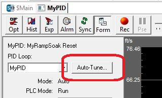
The PID View dialog provides an interface to the Autotune dialog which handles the auto-tune process for the designated loop. Click the Auto-tune... button to open the Auto-Tune dialog.
Note: Before running an auto-tune cycle make sure the process being controlled is relatively stable.
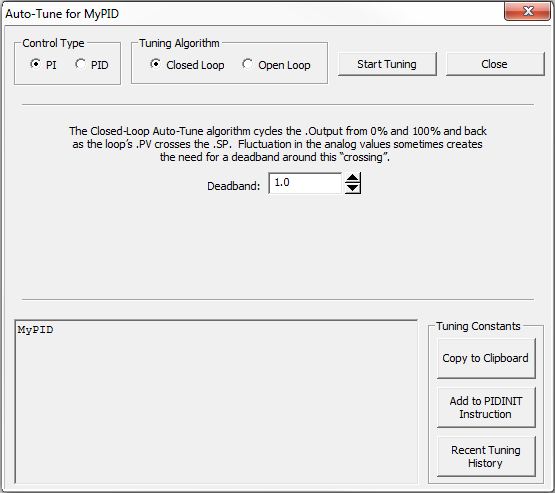
Process Control Type (PI or PID)
Selects which of the following sets of control variables use in the Autotune cycle:
Which Tuning Algorithm (Closed Loop or Open Loop)
The Closed Loop algorithm imposes a square wave on the output. Each transition of the output occurs when the PV value crosses over/under the SP value. Therefore, the frequency of the limit cycle is roughly proportional to the mass of the process. From the PV response, the auto tune function calculates the gains and the sample time. Specifically, the auto tune function examines the direction of the offset of the PV from the SP then takes control of the control output and induces a full-span step change in the opposite direction. Each time the sign of the error (SP - PV) changes, the output changes full-span in the opposite direction. This proceeds through three full cycles. The auto tune function then computes the Gain according to the Ziegler-Nichols equations for a PI or PID type as specified.
Note: Before running the closed loop Auto-tune cycle the Process Variable (PV) and Setpoint (SP) values must be no more than 5% of the full scale difference apart. The PV must also NOT be so close to either the low end or the high end of it's range that it cannot move a full step change above and below the SP.
Note: If the .PV value fluctuates rapidly, use the First Order Filter (FILTER) instruction or the Deadband option below to stabilize that value.
Deadband
- the closed-loop auto-tuning algorithm moves the .Output value from 0%
to 100% and back as the PID Loop's .PV values crosses the .SP value. Any
fluctuation in the analog input used as the .PV value can cause unintended
'crossings'. These fluctuations can be handled by adding a deadband. The
deadband value is specified in tenths of a percent of the range of the
.PV and .SP values.
The range of values in 0 (no deadband) to 100 (10.0%). The deadband value
is also mapped into the system location $TuneDeadBand (DST45).
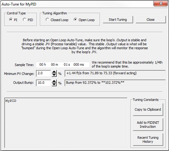
The Open Loop algorithm induces the specified change in the output and observes the responses of the PV at the prescribed interval. Then from the peak change to the PV response, the auto tune function calculates the new tuning constants using the Ziegler-Nichols equations for a PI or PID type as specified.
Sample Time: is the interval at which the .PV value will be sampled to determine the peak change to the PV. The recommended Sample Time is 1/4 of the current PID Loop's .SampleTime value.
Minimum PV Change: is the minimum size change to the .PV value that is required to signal a successful auto-tune. This value is specified as % of the current .PV value. The field to the right will display the current .PV % value.
Output Bump: is the size of the change to make to the output. This value is specified as % of the current .Output value. The field to the right will display the current .Output % value that it will be set to.
Note: The Setpoint (SP) value should be more than 5% of the Process Variable (PV) range away from the actual PV before starting the open loop auto tune process. The PV must also NOT be so close to either the low end or the high end of it's range that it cannot move a full step change above and below the SP.
Click the Start Tuning button to begin the auto-tune process for the currently selected PID loop.
Note: Before running an auto-tune cycle make sure the process that is being controlled is operating within the range of control that is expected..
Click the Close button to dismiss the Auto-tune dialog without running the auto-tune cycle, none of the tuning constants will be changed.
What Happens After a Successful Auto-tune
Each time the Auto-tune process successfully completes the following things happen:
-
the previous values for Gain (P), Reset (I), Rate (D) and the Sample Time are saved in the Recent Tuning History
-
the new values for Gain (P), Reset (I), Rate (D) and the Sample Time are written to the Closed Loop Controller's .Gain, .Reset, .Rate and .SampleTime structure members respectively
At that point the options located in the Tuning Constants group allow for some additional actions with the new tuning constants.
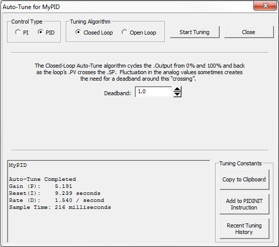
Copy to Clipboard - click this button to copy the Loop Name and the tuning constant results to the Windows clipboard in plain text format. This data can then be pasted into a different Windows application. The following is an example of the data that will be placed on the clipboard::
SimPID
Auto-Tune Completed
Gain
Reset (I):
Rate
Sample Time:
Optionally Add PIDINIT Instruction to the Project
Click this button to open the following dialog :
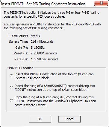
Here you can create a new rung of logic containing a Set PID Tuning Constants (PIDINIT) instruction and place that instruction in the project using one of the following options:
-
Insert this PIDINIT instruction at the top of $FirstScan System Task - inserts a rung containing a Set PID Tuning Constants (PIDINIT) instruction with these new tuning constants already filled in at the top of the $FirstScan code block.
-
Insert the rung of a $FirstScan (ST0) contact driving this PIDINIT instruction at the top of $Main code block - inserts a rung containing an ST0 contact and a Set PID Tuning Constants (PIDINIT) instruction with these new tuning constants already filled in at the top to the $FirstScan code block.
Note: this option requires that the project be in Edit Mode
-
Copy the rung of a $FirstScan (ST0) contact driving this PIDINIT instruction into the Windows Clipboard, so I can paste it where I want - adds a rung containing an ST0 contact and a Set PID Tuning Constants (PIDINIT) instruction with these new tuning constants already filled in to the Windows clipboard. The contents of the clipboard can then be pasted into any code-block in the project.
Recent Tuning History
The Do-more CPU keeps track of all of the changes made to the
Gain (P), Reset (I), Rate (D), and Sample Time values by the following
actions:
-
each time the Autotune process successfully completes, the new values for the tuning constants will be stored in the recent tuning history
-
each time the 'Write to PLC' button on the PID View is used to write new tuning constants, the new values for the tuning constants will be stored in the recent tuning history
-
each time Revert operation (described below) is used to roll back to a previous set of values, the vales that are reverted to will be stored in the recent tuning history
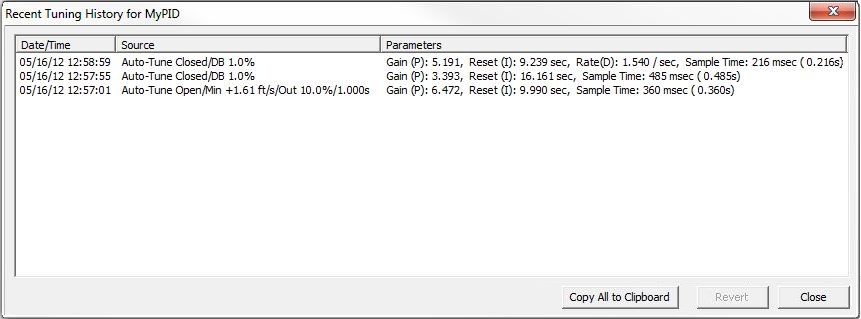
Clicking the Recent Tuning History button will invoke the above dialog for the PID loop. This dialog displays all of the changes made to the tuning constants since the PID View was opened. The Recent Tuning History values are only saved while the PID View dialog is open, as soon as the PID View is closed the Recent Tuning History values will be lost.
Click the Copy All to Clipboard button to store all of the contents of the Recent Tuning History dialog to the Windows clipboard, which can then be pasted into a separate application (e.g. NotePad).
Click to highlight one of the entries then click the Revert button to restore the tuning constants in that selection back to the controller.
Click the Close button to dismiss the dialog.
Once the Auto-tune cycle has completed, the following dialog will then be displayed:

It presents four options for setting the PID loop's mode.
They are:
-
Return Control to the Ladder Program puts the control of the PID Loop back under control of the ladder logic diagram, that is, if the PID instruction has power-flow the loop will go to Auto. If the PID instruction does not have power-flow, the loop will go to Manual mode.
-
Override Loop Mode as Auto will override the ladder logic control of the PID loop and set the loop's mode to Auto. The loop calculation is still being performed.
-
Override Loop Mode as Manual will override the ladder logic control of the PID loop and set the loop's mode to Manual. The loop calculation is not performed, the PID View, an HMI, or some other device is assumed to be controlling the loop.
-
Recent Tuning History opens the Recent Tuning dialog that displays all of the changes that have been made to the Tuning constants during the current editing session, and allows the programmer to roll-back the tuning constants to a previous set.
See Also:
Process Control Instruction Set
Using Autotune
Using the PID Process Simulator
Related Topics:
Instructions for PID Calculations and Managing Tuning Constants
PIDINIT - Set PID Tuning Constants
Alarm Handlers
Input and Output Value Limiters
DEADBAND - Set Outside Deadband
Noise Suppression
INTEGRAT - Integrate Over Time
Ramp / Soak Profiles - up to 250 steps per Profile
Input and Output Scaling
Analog Control using a Discrete Output
TIMEPROP - Time Proportional Control