Topic: DMD0175

ONDTMR - On Delay Timer
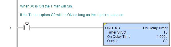
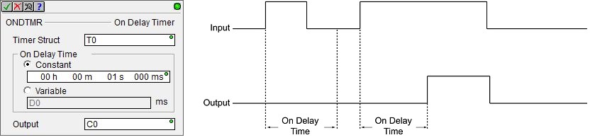
The On Delay Timer (ONDTMR) instruction is used to "delays turning on" an output by accumulating time upward from 0 toward a preset value then turning ON the output. The instruction has a single ladder logic input leg which both enables and resets the Timer. If the input logic is ON, the Timer is enabled and will accumulate time upward from 0 toward a preset value. When the preset value is reached the output will come ON and will remain ON until the input logic goes OFF. When the input logic is OFF, the Timer will reset, the Timer's accumulator value will return to 0, and the Timer's associated structure fields will reset. If the input logic goes OFF before the Timer preset is reached the output will remain OFF.
When a new Timer is added to the ladder logic the Common Timer Editor will be used. When editing an existing Timer, the following type-specific editor will be used. This can be changed in the View -> Options -> Ladder tab -> Editing section by selecting either Use only with new Timers (the default) or Use with new and existing Timers
Parameters:
Note: Use the F9 key or click the 'three dot box' at the right edge of the parameter field to open the Default Element Selection Tool (the Element Picker or the Element Browser) or use the Down-Arrow key (Auto-Complete) on any parameter field to see a complete list of the memory locations that are valid for that parameter of the instruction.
Timer Struct specifies which Timer number to edit, and by extension, the name of the Timer's associated structure. This can be any of the System-created Timers, or any user-created Timer. The default Memory Configuration contains 255 predefined Timers named T0 through T255.
On Delay Time is the amount of time after which you want the specified Output to come ON. All Timers have a resolution of 1 millisecond. The maximum value for a Preset is 2,147,483,647 milliseconds. The Preset value can be specified in one of two ways:
Constant means the Preset is a fixed amount of time and can only be changed by editing the instruction. The Preset value is specified using the Time format (HH : MM : SS : mmm). The maximum Time value in this form is 569 hours, 31 minutes, 23 seconds, and 647 milliseconds. If needed, the value entered for the Timer Preset will be normalized to its standard value. For example, if you entered a value of 97 Seconds, that value will be converted and displayed as 1 Minute and 37 Seconds. When editing the Constant Preset value the following keystrokes are available to make entering the value easier and faster:h, m. s, and mm move the edit cursor to the Hours, Minutes, Seconds or milliseconds fields respectively.
Variable allows the Preset to be changed while the PLC is running. The Preset is specified as a numeric memory location that will contain the total number of milliseconds desired (from 0 to 2,147,483,647). This can be any readable numeric location.
Output is the Bit location that will be turned ON after the On Delay Time has expired. This can be any writable bit location.
Termination Scan Behavior:
All Timers - with one exception - have termination logic. This means if the Timer instruction is contained within a Program, a Task, or a Stage, the Timer will automatically be reset any time that Program, Task, or Stage stops executing because of an End Program, End Task, or Disable Stage respectively.
The Global Accumulating Up Timer (TMRAG) instruction does NOT have termination logic, meaning that it will retain it's accumulated time and the state of it's internal flags even if it is contained within a Program, a Task, or a Stage, that is disabled.
Refer to the Help topic on Termination Behavior for detailed information on the programming elements that have termination logic.
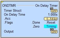
Status Display:
The yellow triangle in the upper left corner indicates this is a Multi-Scan instruction.
Timer Structure Members:
All Timers have an associated structure with fields that can be used in the ladder program. The structure fields are updated whenever the Timer instruction is processed in the PLC scan. The syntax for using them is <Timer structure>.<field name>, for example, T7.Acc.
.Acc (read/write) is a 32-bit signed value that represents the total accumulated time whenever the Timer is enabled. If the Timer is still enabled after the Preset is reached, the .Acc value keeps incrementing to a maximum of 2,147,483,647 ms (596 hrs, 31 min, 23.647s), it does not wrap.
.Done (read-only) will be ON any time the Timer's accumulator value (.Acc) is greater than or equal to the Timer's Preset value.
.Zero (read-only) will be ON any time the Timer's accumulator value (.Acc) is 0.
.Timing (read-only) will be ON if the Timer is enabled, and is NOT being held in Reset by the Reset Input leg or a Reset Timer (RSTT) instruction. Will remain ON after .Done turns ON.
.Reset (read-only) will be ON if the reset (RST) leg's input logic is TRUE, or if the Timer is being reset by a Reset Timer (RSTT) instruction.
.TT (read-only) will be ON if the Timer is enabled, and is NOT being held in Reset by the Reset Input leg or a Reset Timer (RSTT) instruction. Will turn OFF when .DN turns ON.
.EN (read-only) will be ON any time the Timer's input logic is TRUE, and the Timer is NOT being held in Reset by the Reset Input leg or a Reset Timer (RSTT) instruction.
.DN (read-only) will be ON any time the Timer's input logic is ON and it's accumulator value (.Acc) is greater than or equal to the Timer's Preset value.
See Also:
ONDTMR - On Delay Timer
Related Topics:
TMRADOWN - Accumulating Down Timer
TMRAG - Global Accumulating Up Timer
Rung Example: