Topic: DMD0433

INI - Immediate Discrete Input
The Immediate Discrete Input (INI) instruction will immediately read the ON / OFF status of the specified discrete input at the instant this instruction is executed in the PLC scan instead of getting its status from the image register that gets updated as part of the normal I/O cycle at the top of the PLC scan. The instruction can only use discrete input points that support Interrupt functionality - for example the on-board discrete inputs of the BRX PLCs and the inputs on a BRX HSIO module (BX-HSIO1, BX-HSIO2, BX-HSIO4).
Note: the default configuration for on-board discrete inputs has an Input Filter value of 25ms. You can change the filter value to a lower value - for quicker response - in the System Configuration .
Note: for scan consistency, when the instruction is executed it will NOT update the image register location for the Discrete Input being read, only the Discrete Result will be updated.
Parameters:
Note: Use the F9 key or click the 'three dot box' at the right edge of the parameter field to open the Default Element Selection Tool (the Element Picker or the Element Browser) or use the Down-Arrow key (Auto-Complete) on any parameter field to see a complete list of the memory locations that are valid for that parameter of the instruction.
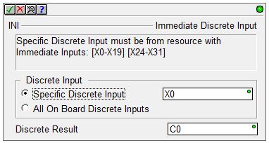
Selecting Specific Discrete Input specifies the discrete input point to immediately read. This can be any of the on-board discrete inputs of BRX CPUs or any of the inputs on a BRX HSIO module (BX-HSIO1, BX-HSIO2, BX-HSIO4). The section at the top of the editor will show the all of the discrete inputs that can be selected, the on-board inputs and the inputs from any BRX HSIO module in the system. Discrete Result selects the Bit memory location to store the On / OFF state of the discrete input just read. This can be any Bit memory location or a specific bit of a numeric memory location using an appropriate cast operator (D0:0 would use Bit 0 of D0).
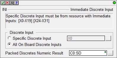
Selecting All On Board Discrete Inputs will read the ON / OFF state of all of the on-board discrete inputs at the same time. The result will be stored as successive bits in a numeric memory location. The Packed Discrete Numeric Result selects a numeric memory location to use. This can be any numeric memory location or any bit location with an appropriate cast operator (C0:UW would use 16 consecutive bit locations starting at C0 : C0 - C15). The size of the numeric memory location required to hold the ON / OFF state for all of the discrete inputs is determined by the model of the PLC or I/O module being used:
BX-DM1E-M has no on board discrete inputs so this function will not return any useful data.
BX-DM1E-10 has six (6) on board discrete inputs, so a Byte location (or a larger numeric memory location with a :UB cast operator) is required. The 2 unused bit locations in the Byte will be OFF.
BX-DM1E-18 has ten (10) on board discrete inputs, so a Word location (or a larger numeric memory location with a :UW cast operator) is required. The 6 unused bit locations in the Word will be OFF.
BX-DM1E-36 has twenty (20) on board discrete inputs, so a DWord numeric location is required. The 12 unused bit locations in the DWord will be OFF.
See Also:
INI - Immediate Discrete Input
Related Topics:
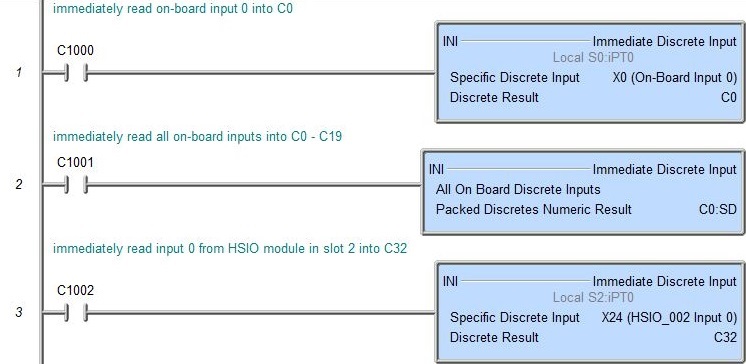
Rung Example: